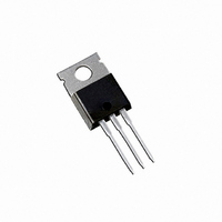
IRFB42N20DPBF International Rectifier, IRFB42N20DPBF Datasheet - Page 8

IRFB42N20DPBF
Manufacturer Part Number
IRFB42N20DPBF
Description
MOSFET N-CH 200V 44A TO-220AB
Manufacturer
International Rectifier
Series
HEXFET®r
Specifications of IRFB42N20DPBF
Fet Type
MOSFET N-Channel, Metal Oxide
Fet Feature
Standard
Rds On (max) @ Id, Vgs
55 mOhm @ 26A, 10V
Drain To Source Voltage (vdss)
200V
Current - Continuous Drain (id) @ 25° C
44A
Vgs(th) (max) @ Id
5.5V @ 250µA
Gate Charge (qg) @ Vgs
140nC @ 10V
Input Capacitance (ciss) @ Vds
3430pF @ 25V
Power - Max
2.4W
Mounting Type
Through Hole
Package / Case
TO-220-3 (Straight Leads)
Channel Type
N
Current, Drain
44 A
Gate Charge, Total
91 nC
Package Type
TO-220AB
Polarization
N-Channel
Power Dissipation
330 W
Resistance, Drain To Source On
0.055 Ohm
Resistance, Thermal, Junction To Case
0.45 °C/W
Temperature, Operating, Maximum
+175 °C
Temperature, Operating, Minimum
-55 °C
Time, Turn-off Delay
29 ns
Time, Turn-on Delay
18 ns
Transconductance, Forward
21 S
Voltage, Breakdown, Drain To Source
200 V
Voltage, Drain To Source
200 V
Voltage, Forward, Diode
1.3 V
Voltage, Gate To Source
±30 V
Lead Free Status / RoHS Status
Lead free / RoHS Compliant
Other names
*IRFB42N20DPBF
IRFB42N20DPbF
‚
Notes:
IR WORLD HEADQUARTERS: 233 Kansas St., El Segundo, California 90245, USA Tel: (310) 252-7105
8
Repetitive rating; pulse width limited by
R
max. junction temperature.
Starting T
G
= 25Ω, I
J
= 25°C, L = 1.45mH
AS
NOTES:
1 DIMENSIONING & TOLERANCING PER ANSI Y14.5M, 1982.
2 CONTROLLING DIMENSION : INCH
= 26A, V
15.24 (.600)
14.84 (.584)
14.09 (.555)
13.47 (.530)
E XAMP L E :
2.87 (.113)
2.62 (.103)
3X
2.54 (.100)
1.40 (.055)
1.15 (.045)
2X
GS
T H IS IS AN IR F 1010
L OT CODE 1789
AS S E MB L E D ON WW 19, 1997
IN T H E AS S E MB L Y L INE "C"
Note: "P" in assembly line
position indicates "Lead-Free"
=10V
10.54 (.415)
10.29 (.405)
1
2
3
4
3X
This product has been designed and qualified for the Industrial market.
0.36 (.014)
6.47 (.255)
6.10 (.240)
0.93 (.037)
0.69 (.027)
1.15 (.045)
4.06 (.160)
3.55 (.140)
MIN
3.78 (.149)
3.54 (.139)
M
- A -
ƒ
„
…
B A M
Pulse width ≤ 400µs; duty cycle ≤ 2%.
I
C
T
as C
SD
Visit us at www.irf.com for sales contact information.7/04
J
oss
Data and specifications subject to change without notice.
INT E RNAT IONAL
≤ 175°C
3 OUTLINE CONFORMS TO JEDEC OUTLINE TO-220AB.
4 HEATSINK & LEAD MEASUREMENTS DO NOT INCLUDE BURRS.
≤ 26A, di/dt ≤ 110A/µs, V
Qualification Standards can be found on IR’s Web site.
R E CT IF IE R
AS S E MB L Y
L OT CODE
eff. is a fixed capacitance that gives the same charging time
oss
L OGO
while V
4.69 (.185)
4.20 (.165)
DS
is rising from 0 to 80% V
- B -
1.32 (.052)
1.22 (.048)
2.92 (.115)
2.64 (.104)
3X
HEXFET
1- GATE
2- DRAIN
3- SOURCE
4- DRAIN
0.55 (.022)
0.46 (.018)
LEAD ASSIGNMENTS
DD
LEAD ASSIGNMENTS
1 - GATE
2 - DRAIN
3 - SOURCE
4 - DRAIN
≤ V
DAT E CODE
YE AR 7 = 1997
WE E K 19
L INE C
PART NU MB E R
(BR)DSS
IGBTs, CoPACK
1- GATE
2- COLLECTOR
3- EMITTER
4- COLLECTOR
TAC Fax: (310) 252-7903
,
DSS
www.irf.com


