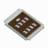
IRF7759L2TR1PBF International Rectifier, IRF7759L2TR1PBF Datasheet - Page 3

IRF7759L2TR1PBF
Manufacturer Part Number
IRF7759L2TR1PBF
Description
MOSFET N-CH 75V 375A DIRECTFET
Manufacturer
International Rectifier
Series
HEXFET®r
Datasheet
1.IRF7759L2TRPBF.pdf
(11 pages)
Specifications of IRF7759L2TR1PBF
Fet Type
MOSFET N-Channel, Metal Oxide
Fet Feature
Standard
Rds On (max) @ Id, Vgs
2.3 mOhm @ 96A, 10V
Drain To Source Voltage (vdss)
75V
Current - Continuous Drain (id) @ 25° C
375A
Vgs(th) (max) @ Id
4V @ 250µA
Gate Charge (qg) @ Vgs
300nC @ 10V
Input Capacitance (ciss) @ Vds
12222pF @ 25V
Power - Max
3.3W
Mounting Type
Surface Mount
Package / Case
DirectFET™ Isometric L8
Transistor Polarity
N-Channel
Drain-source Breakdown Voltage
75 V
Gate-source Breakdown Voltage
20 V
Continuous Drain Current
160 A
Power Dissipation
125 W
Gate Charge Qg
200 nC
Lead Free Status / RoHS Status
Lead free / RoHS Compliant
Other names
IRF7759L2TR1PBFTR
Available stocks
Company
Part Number
Manufacturer
Quantity
Price
Company:
Part Number:
IRF7759L2TR1PBF
Manufacturer:
MXIC
Quantity:
101
ƒ
„
ˆ
ƒ Surface mounted on 1 in. square Cu
board (still air).
P
P
P
T
T
T
R
R
R
R
R
Absolute Maximum Ratings
Thermal Resistance
Notes:
www.irf.com
D
D
D
P
J
STG
θJA
θJA
θJA
θJ-Can
θJ-PCB
Surface mounted on 1 in. square Cu board, steady state.
Used double sided cooling, mounting pad with large heatsink.
T
@T
@T
@T
C
measured with thermocouple incontact with top (Drain) of part.
C
C
A
0.0001
= 25°C
= 25°C
= 100°C
0.001
0.01
0.1
10
1E-006
1
Fig 3. Maximum Effective Transient Thermal Impedance, Junction-to-Case
Power Dissipation
Power Dissipation
Power Dissipation
Peak Soldering Temperature
Operating Junction and
Storage Temperature Range
Junction-to-Ambient
Junction-to-Ambient
Junction-to-Ambient
Junction-to-Can
Junction-to-PCB Mounted
D = 0.50
0.10
0.05
0.20
0.02
0.01
1E-005
SINGLE PULSE
( THERMAL RESPONSE )
l
c
e
j
k
Parameter
Parameter
0.0001
t 1 , Rectangular Pulse Duration (sec)
‰ Mounted on minimum footprint full size board with metalized
back and with small clip heatsink. (still air)
τ
J
τ
J
τ
1
Ci= τi/Ri
τ
1
Ci
‰
Š
0.001
i/Ri
back and with small clip heatsink.
Mounted on minimum footprint full size board with metalized
R
R
1
R
θ
1
is measured at
τ
2
τ
R
2
2
R
2
R
τ
3
3
R
τ
3
0.01
3
T
J
of approximately 90°C.
τ
Typ.
12.5
R
4
–––
–––
–––
20
τ
4
Notes:
1. Duty Factor D = t1/t2
2. Peak Tj = P dm x Zthjc + Tc
R
4
4
τ
C
τ
-55 to + 175
Ri (°C/W)
0.10804
0.61403
0.45202
0.00001
Max.
125
270
3.3
63
0.1
„
Max.
–––
–––
1.2
0.5
τi (sec)
0.000171
0.053914
0.006099
0.036168
45
1
Units
Units
°C/W
°C
W
3


