OS533E NEWPORT ELECTRONICS, OS533E Datasheet
OS533E
Specifications of OS533E


OS533E Summary of contents
Page 1
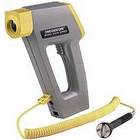
... TM Shown with Built-in Distance Measuring Option and Digital Video Camera Attachment OS530LE, OS532E, OS53xE-CF, OS533E, OS534E, OS530HRE, OS523E, OS524E OMEGASCOPE Handheld Infrared Thermometer User’ s Guide Shop online at omega.com e-mail: info@omega.com For latest product manuals: omegamanual.info ® ...
Page 2
OMEGAnet ® omega.com U.S.A.: One Omega Drive, Box 4047 ISO 9001 Certified Stamford, CT 06907-0047 Tel: (203) 359-1660 e-mail: info@omega.com Canada: 976 Bergar Laval (Quebec) H7L 5A1, Canada Tel: (514) 856-6928 e-mail: info@omega.ca For immediate technical or application assistance: U.S.A. ...
Page 3
Unpacking Instructions n4 Notes ...
Page 4
... OS530/OS520 Series Handheld Infrared Thermometer (1) • AA Size Lithium Batteries (4) • Soft Cover Carrying Case (1) • Analog Cable (1) • RS232 Cable (only for OS533E, OS534E, OS523E, OS524E) • CD Software (only for OS533E, OS534E, OS523E, OS524E) • Quick Start Manual (1) Accessories Model No. UNI-ADAP-9V ...
Page 5
ii ...
Page 6
... Thermocouple Input (OS532E, OS533E, OS534E) 2.3.10 Using the Alarm Functions 2.3.11 Using Ambient Target Temperature Compensation (OS533E, OS534E, OS523E, OS524E) 2.3.12 PC Interface Software (OS533E, OS534E, OS523E, OS524E) 2.3.13 PC Interface Commands 2.3.14 Storing Temperature Data on Command (OS533E, OS534E, OS523E, OS524E) 2.3.15 Logging Temperature Data in Real Time (OS533E, OS534E, OS523E, OS524E) 2 ...
Page 7
TABLE OF CONTENTS Chapter 5 Digital Video Camera 5.1 Camera Parts 5.2 Battery Installation 5.3 Turning Camera ON/OFF 5.4 Menu Selection Chapter 6 Maintenance 6.1 Replacing the Batteries 6.2 Cleaning the Lens 6.3 Calibrating the Thermometer 6.4 Servicing the Laser ...
Page 8
... Introduction The OS530E/OS520E series Handheld Infrared (IR) Thermometers provide non-contact temperature measurements up to 4500°F. They offer effective solutions for many non-contact temperature applications, including the following: • Predictive Maintenance: Tracking temperature shifts which indicate pending failure in solenoid valves. • Energy Auditing: Locating wall insulation voids to reduce building heating costs. • ...
Page 9
... Optional Optional OS533E OS534E ±1% rdg ±1% rdg adjustable adjustable standard standard 20:1 30:1 standard standard standard standard standard standard standard standard standard standard ...
Page 10
... Dot std std std std --- --- Optional General Description OS533E-CF OS534E-CF ±1% rdg ±1% rdg -10 to 1000°F -10 to 1600°F -23 to 538°C -23 to 871°C Adjustable Adjustable 1°F or 1°C 1°F or 1°C std 0.15"@6" ...
Page 11
General Description Features Accuracy Range Emissivity Backlit Dual Display Distance to Spot Size Ratio Differential Temperature Min/Max Temperature Average Temperature High Alarm Low Alarm Audible Alarm & Indicator Ambient Target Temperature Compensation Analog Output RS-232 Output Thermocouple Input Data ...
Page 12
Parts of the Thermometer 1.2.1 Front of the Thermometer “V” Groove Lens Rubber Boot Built-in Distance Module (Optional) Distance Power Switch Trigger Battery Compartment Door Tripod Mount Figure 1-1. OS530E/OS520E Series Handheld Infrared Thermometer Front View The display is ...
Page 13
General Description Figure 1-2. Display and Keypad View Table 1-2. Display Details Key ➀ Display Mode displays one of the following: E (Emissivity) d_F (distance in Feet) (Distance in Meters) d_M LSR (Laser either flashing or continuous) LAL (Low ...
Page 14
... Figure 1-3. OS530E/OS520E Series Handheld Infrared Thermometer General Description Thermocouple Input Socket (SMP) (standard on OS532E, OS533E, OS534E) ac Adapter Input Jack Analog Output Jack (1mV/deg) RS-232 Phone Jack (standard on OS533E, OS534E, OS523E, OS524E) Various Views 1 Laser Power Switch Laser Beam Aperture 1-7 ...
Page 15
General Description 1-8 Notes ...
Page 16
Using the Handheld Infrared Thermometer 2.1 How to Power the Thermometer 2.1.1 Battery Operation Invert the thermometer and install 4 fresh AA size batteries as shown in Figure 2-1. Make sure the batteries’ polarities are correct, the batteries are not ...
Page 17
... Sighting. 2. The field of view of the thermometer should fall within the area of the target being measured as shown in Figure 2-2. Figures 2-3 through 2-9 show the field of view vs distance for the various thermometers. Figure 2-3. Field of View OS532E, OS530LE 2-2 Field of View Target ...
Page 18
... DIAMETER MEASURED AT 90% ENERGY 40 DISTANCE: SENSOR TO OBJECT (CM) Figure 2-4 Field of View OS533E, OS530HRE ** Measurement distance is from the outside surface of the rubber boot. Figure 2-5 Field of View OS534E, OS523E 3.0" 2.4" 1.8" 4.0 6 ...
Page 19
Using the Handheld Infrared Thermometer 0 0.9" 22 *SPOT DIAMETER MEASURED 0 0.9"@ 0 0.9" *SPOT DIAMETER MEASURED 2-4 DISTANCE: SENSOR LENS TO OBJECT (in.) 3" 6" 9" .39" .45" .15" 3.9 11.5 9.9 AT 90% ENERGY 7.6 15.2 ...
Page 20
Using the Handheld Infrared Thermometer DISTANCE: SENSOR TO OBJECT (FT) 3’ 0’ 2’ 5’ .35"@ 24" 1.6" .9" .8" 9mm @ 610mm *SPOT DIAMETER MEASURED AT 90% ENERGY 0 .61 1.0 1.5 DISTANCE: SENSOR TO OBJECT (M) ...
Page 21
Using the Handheld Infrared Thermometer 3. The target temperature and emissivity are displayed on the LCD. Determine the emissivity of the target (refer to Appendix B). Press the key to increment the target emissivity. Press the decrement the target ...
Page 22
Static Surface Scan – Measures the temperature across a static 1. Aim the thermometer at a starting point and pull the trigger. Press the LOCK 2. If necessary, adjust the emissivity. 3. Slowly move the thermometer so that the ...
Page 23
... If necessary, adjust the emissivity. 5. The thermometer is now set up for unattended monitoring of temperature over time. You can also download the temperature to a Serial Printer for further analysis (Models OS533E, OS534E, OS523E, OS524E). 6. After all data is taken, press the 2.3 Real Time Mode (Active Operation) Definition: Real Time Mode is the active operational mode of the thermometer ...
Page 24
... Using the Handheld Infrared Thermometer Table 2-1. Functional Flow Chart when the Trigger is Pulled (Real Time Mode) OS530HRE OS530LE, OS532E OS533E OS524E OS523E, OS534E, 2 2-9 ...
Page 25
... FUNC LCK ☞ FUNC LCK Figure 2-13. Visual Function Flow Chart * While in these 7 modes: MODE HAL ☞ FUNC (Models OS530LE, OS530HRE) ☞ FUNC (Model OS532E) LAL FUNC FUNC PRN ☞ FUNC (Model OS533E) ☞ FUNC (Models on OS534E, OS523E, OS524E) ☞ FUNC ...
Page 26
Adjusting Emissivity Refer to Appendices B and C for information on emissivity. 1. Determine the emissivity of the target. °F 2. Aim at the target and pull the trigger necessary, press the or press the The Emissivity ...
Page 27
Using the Handheld Infrared Thermometer 2.3.4 Using the Distance Function • There should be a clean, open line of sight from the distance LCK • For accurate distance measurement readings, the surface • Distance measurement can not be taken ...
Page 28
The built-in version (-DM integal part of the thermometer, and distance measurment is made using the LCK thermometer's keypad the d_F or d_M display menu. There is a slide power switch on the side of the ...
Page 29
Using the Handheld Infrared Thermometer 0' 0.5" Figure 2-17. Field of View of Distance Meter HH-DM Distance Meter HH-DM Figure 2-18. Line of Sight of the Infrared Thermometer 2-14 DISTANCE METER TO OBJECT (FT) ...
Page 30
Laser Sighting Status In the LSR display menu, the status of the laser sighting is shown either as Flashing (FLS) or continuous (on). Pressing the change the status from flashing to continuous and vise versa. There is a slide ...
Page 31
... During the time that the thermometer displays either d_F, d_M, LSR, MAX, MIN, dIF, AVG temperatures, press the to turn the display backlighting ON/OFF. 2.3.9 Thermocouple Input (OS532E, OS533E, OS534E) The thermometer accepts thermocouple input. It displays thermocouple temperature and the target temperature (via infrared) simultaneously ...
Page 32
Using the Alarm Functions The thermometer provides audible and visible alarm indications. • To set the high alarm value: HAL °F 1. Pull the trigger. Then press and hold the the High Alarm Display Mode (HAL) appears. 2. Press ...
Page 33
... Using the Handheld Infrared Thermometer • To set the low alarm value: (OS533E, OS534E, OS523E, OS524E): °F 1. LAL 2-18 NOTE The high alarm setpoint does not change when the thermometer is turned off. However, when the batteries are replaced reset to the default value ...
Page 34
... Using Ambient Target Temperature Compensation (OS533E, OS534E, OS523E, OS524E) Use the Ambient Target Temperature Compensation °F ATC (AMB) of these conditions are required: • The target has a low emissivity. • The ambient temperature around the target is much To set and activate the Ambient Target Temperature Compensation Mode: 1 ...
Page 35
... Using the Handheld Infrared Thermometer 8. °F ATC 9. 10. 11. 2.3.12 PC Interface Software (OS533E, OS534E, OS523E, OS524E) Software Installation: In order to install the PC interface software (IRTM), the PC should have the following minimum requirements: Operating System: Windows 98SE, 2000, NT4. RAM Hard disk with a minimum free space Place the CD into the CDROM drive ...
Page 36
Sending temperature data Real Time: 1. From Windows Operation System Start Infrared Temperature Measurement 2. Check the RS232 connection between the infrared thermometer and the PC. Select your serial COM Port number from the Communication ...
Page 37
Using the Handheld Infrared Thermometer The transmitted temperature data is the average temperature for the specified data transmission interval. The data transmission interval (PRN) can be set any where from 1 to 1999 seconds. You can save the data ...
Page 38
Menu Description File Save Data As... Save the collected temperature data in one of the formats: Excel File (.xls), Text File (.txt), Data File (.dat) Exit temperature data? View Show (Hide) Data File Show or Hide the Data Table on ...
Page 39
Using the Handheld Infrared Thermometer Tool Stop Data Transmission to Change Parameters Stop data transmission to be able to change parameter settings like E, HAL, LAL, etc. Any change of parameter settings will reflect on the thermometer's display. When ...
Page 40
PC Interface Commands You can communicate directly from the PC to the infrared thermometer. Here are the Comm port settings and communication commands from the PC: Baud rate: 9600 Data: 8 Bits One Stop Bit No Parity All the ...
Page 41
Using the Handheld Infrared Thermometer String Description E:95; Emissivity is 0.95 MAX:78; Maximum temperature is 78 MIN:65; Minimum temperature is 65 DIF:13; Differential temperature is 13 AVG:72; Average temperature is 72 DIS:1144; Distance is 11.44 feet (always in feet) ...
Page 42
Storing Temperature Data on Command (OS534E, OS523E, OS524E) The thermometer can store up to 800 temperature data points on command. This data is stored in the non-volatile °F memory, so removing the batteries will not affect or erase this ...
Page 43
Using the Handheld Infrared Thermometer 2.3.15 Logging Temperature Data in Real Time (OS523E, OS524E,OS534E) The thermometer can log temperature data in real time. The on logged data is stored in the non-volatile memory, so °F LCK removing the batteries ...
Page 44
Erasing the Temperature Data from Memory The user can erase all 800 temperature data points in memory at any time by using the following procedure: 1. Pull the trigger and press the icon will appear. 2. Press the disply ...
Page 45
Using the Handheld Infrared Thermometer 2.4 Recall Mode (Passive Operation) Definition: Recall Mode is the passive operational mode of the thermometer. In this mode, you may review the most recently stored temperature data and parameters. Pull Trigger Real Time ...
Page 46
... Using the Handheld Infrared Thermometer Table 2-2. Functional Flow Chart (Recall Mode) OS530HRE OS530LE, OS532E OS533E OS524E OS523E, OS534E, 2 2-31 ...
Page 47
Using the Handheld Infrared Thermometer 2.4.1 Reviewing the Last Parameters The thermometer stores the last temperature measured in the real time mode (refer to Table 2-1). This temperature °F can be recalled by pressing the - Press the temperature ...
Page 48
Warnings and Cautions You may receive harmful laser radiation exposure if you do not adhere to the warnings listed below: • USE OF CONTROLS OR ADJUSTMENTS OR PERFORMANCE OF PROCEDURES OTHER THAN THOSE SPECIFIED HERE MAY RESULT IN HAZARDOUS ...
Page 49
Laser Sighting 3.2 Description The Laser Sighting is built into the thermometer. It provides a visual indication of the field of view of the thermometer. Aiming at distant targets ( feet) becomes much easier by using the ...
Page 50
Operating the Laser Sighting 1. Set the laser power switch to the ON position as shown in Figure 3-2. 2. Aim at the target and pull the trigger. 3. The laser beam and the red power indicator LED will ...
Page 51
Laser Sighting The Laser Sighting turns on only when used with the thermometer. The module does not turn on by itself. The line of sight of the thermometer does not coincide with that of the Laser Sighting, as shown ...
Page 52
Sighting Scope The Sighting scope is an accessory for the thermometer. It provides a visual indication of the target being measured. Aiming at distant targets (up to 200 feet) becomes much easier by using the Sighting scope. 4.2 Installing ...
Page 53
Sighting Scope 4-2 Pair of Mounting Clamps Figure 4-1. Installing the Sighting Scope Line of sight of the sighting scope 1 11/16 (42.8 mm) Line of sight of the thermometer ...
Page 54
Camera Parts (1) Shutter (2) Lens (3) Focus (4) Mirror (5) Microphone (6) View finder (7) LCD display (8) LED light (9) Record button (10) MENU button (11) USB port (12) CF memory card slot (13) AV-out port (14) ...
Page 55
Digital Video Camera For additional information please refer to the Digital Video Camera's manual available on the accompanying CD. 5-2 (1) Exit MENU (2) Playback (3) Voice Record (4) Picture Resolution N (5) Picture Quality (6) Self-Timer (7) Erase ...
Page 56
Replacing the Batteries When you change the batteries, all of the set parameters (i.e. emissivity, high alarm, low alarm, Target Ambient Temperature) will be reset to the default values. For your convenience, you may want to write down all ...
Page 57
Maintenance 6.2 Cleaning the Lens Although all lenses are quite durable, take care to prevent scratching when cleaning them. To clean the lens: 1. Blow off loose particles, using clean air. 2. Gently brush off remaining particles, using a ...
Page 58
THERMOMETER Problem The thermometer does not turn on (No Display) - The icon flashes. - The thermometer beeps intermittently. - The thermometer flashes in the Main Display. Troubleshooting Guide Solution 1a. Properly install fresh batteries. 1b. If operating under ac ...
Page 59
Troubleshooting Guide Problem The thermometer is “locked up” (the display is “frozen”). The display is either erratic or stays at one reading. You can expect to see and hear the following: 7-2 Solution Remove and reinstall the batteries or ...
Page 60
Problem The temperature reading is erratic. The thermometer has just been moved from one extreme temperature to room temperature [0°C or 50°C (32°F or 122°F)] or vice versa. The temperature reading is erratic. The thermometer has just been moved from ...
Page 61
Troubleshooting Guide 7-4 Notes ...
Page 62
... OS530HRE) 100 msec microns (2 to 2.5 microns, OS524) Type K, -18 to 871° 1600°F) (OS532E, OS533E, OS534E only) SMP Connector ±3°C (±5°F) 2 seconds 0°C to 50°C (32°F to 122°F) ...
Page 63
... Set and enabled via keypad All models: High alarm standard, with audible and visual indication OS533E, OS534E Low alarm standard, with OS523E, OS524E: audible and visual indication OS534E, OS523E Up to 800 temperature data OS524E: points. ”V” groove on top of the thermometer or use Laser Sighting 1 mV/° ...
Page 64
Output voltage: Output plug (female): Low Battery Indicator: Alkaline Batery Life at 24°C (75·°F) ambient temperature Without Laser Sighting With Laser Sighting With LCD backlight & no laser With Built-in Distance Module With Built-in Distance Moduler active Lithium ...
Page 65
Specifications LASER SIGHTING Wavelength (Color): Operating Distance: Laser Dot Laser Circle Max. Output Optical Power: <1mW at 75°F ambient temperature, European Classification: Maximum Operating Current: 25mA at 5.5 V FDA Classification: Beam Diameter: Beam Divergence: Laser Configuration: Laser Status: ...
Page 66
DISTANCE MEASURING (Built-in-DM) Size Weight Accuracy: Units of Measure: Sensor: Power: Battery Life: Operating ambient temperature: Operating relative humidity: Less than 80% RH DIGITAL VIDEO CAMERA Display: Digit Still Camera: 2M: SXGA: VGA: PC Camera: VGA: QVGA: Digital voice recording: ...
Page 67
Specifications 8-6 Notes ...
Page 68
Key(s) FUNC LOCK F C Press the FUNC key & LOCK the key together LOCK Press the & the keys together F Press and Hold Key C Pull the trigger Release trigger F Release Key C Glossary of Key Strokes ...
Page 69
Glossary of Key Strokes 9-2 Notes ...
Page 70
Appendix: How Infrared Thermometry Works Thermal Radiation Heat is transferred from all objects via radiation in the form of electromagnetic waves or by conduction or convection. All objects having a temperature greater than absolute zero (-273°C, -459° radiate ...
Page 71
A Appendix: How Infrared Thermometry Works Blackbody When thermal radiation falls on an object, part of the energy is transmitted through the object, part is reflected and part is absorbed. A blackbody is defined as an ideal object that absorbs ...
Page 72
Wien’s Displacement Law describes the exact mathematical relationship between the temperature of a blackbody and the wavelength of the maximum intensity radiation. where λ = wavelength measured in microns temperature in Kelvin Calculating Temperature The net thermal ...
Page 73
... All optical devices (e.g. cameras, microscopes, infrared thermometers) have an angle of vision, known as a field of view or FOV, within which they see all objects. In particular, the thermometer will measure a fixed proportion of the energy radiated by all objects within its FOV ...
Page 74
Appendix: Emissivity Values Table B-1 provides guidelines for estimating the emissivity of various common materials. Actual emissivity, especially of metals, can vary greatly depending upon surface finish, oxidation, or the presence of contaminants. Also, emissivity or infrared radiation for some ...
Page 75
B Appendix: Emissivity Values Material Asbestos Board . . . . . . . . . . . . . . . . . . . . . . . . . . . . . . . . . ...
Page 76
Appendix: Determining an Unknown Emissivity In Appendix A, we showed how emissivity is an important parameter in calculating the temperature of an object via infrared means. In this section we discuss how to determine a specific emissivity value. If you ...
Page 77
C Appendix: Determining an Unknown Emissivity Method 3 1. Use this method to measure objects at temperatures below 260°C (500°F). 2. Place a large piece of masking tape on the object (or at least a sample of the object material). ...
Page 78
Method 4 1. Paint a sample of the object material with flat black lacquer paint. 2. Set the emissivity to 0.97 and measure and record the temperature of the painted portion of the sample material - Area ‘A’ in Figure ...
Page 79
C Appendix: Determining an Unknown Emissivity C-4 Notes ...
Page 80
A ac Adapter Input Jack ............. 1-7 Active Operation ...................... 2-9 Aiming Sight “V Groove” 1-2, 1-5 Alarms ........................... 2-16, 2-17 Alkaline Batteries ...... 2-1, 5-1, 6-1 Ambient Target Temperature Compensation .... 2-18, 2-19, 2-28 Analog Output Jack ................. 1-7 ...
Page 81
I Index F Field of View: Diagrams .................... 2-2 to 2-6 Positions ................................ 2-2 Fixed Point Monitoring over Time Measurement ................ 2-8 G Gray Bodies (Objects) ............. A-2 H High Alarm Value, setting ............ .................................. 2-16, 2-27 I Icons: ATC ...
Page 82
M Main Display ............................ 1-4 Modes: Real Time .............................. 2-8 Recall ........................ 2-23, 2-25 Moving Surface Scan ............... 2-7 O Optics ........................................ A-4 P Parameters, reviewing .......... 2-27 PAS Code .................................. 5-2 Passive Operation .................. 2-25 Personal Computer Hookup ................................. ...
Page 83
OMEGA ENGINEERING, INC. warrants this unit to be free of defects in materials and workmanship for a period of 25 months from date of purchase on the base unit and 13 months from date of purchase on Laser Sight Module. ...
Page 84
Where Do I Find Everything I Need for Process Measurement and Control? OMEGA…Of Course! Shop online at omega.com TEMPERATURE Thermocouple, RTD & Thermistor Probes, Connectors, Panels & Assemblies Wire: Thermocouple, RTD & Thermistor Calibrators & Ice Point References Recorders, Controllers ...