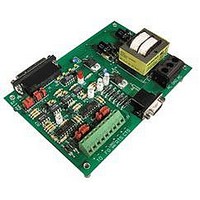
AC8 OPTO 22, AC8 Datasheet - Page 9

AC8
Manufacturer Part Number
AC8
Description
Computers, Interface Cards
Manufacturer
OPTO 22
Datasheet
1.AC8.pdf
(11 pages)
Specifications of AC8
Peak Reflow Compatible (260 C)
No
Leaded Process Compatible
No
Features
Half Duplex Modem Interface, 5VDC
Lead Free Status / RoHS Status
Lead free / RoHS Compliant
Available stocks
Company
Part Number
Manufacturer
Quantity
Price
Part Number:
AC80566 400SLGMB
Manufacturer:
INTEL
Quantity:
20 000
Part Number:
AC80566 533 SLGPT
Manufacturer:
INTEL
Quantity:
20 000
Company:
Part Number:
AC80566-533
Manufacturer:
MITSUMI
Quantity:
1 357
Part Number:
AC80566-533
Manufacturer:
INTEL
Quantity:
20 000
Company:
Part Number:
AC80566-533/SLB6P
Manufacturer:
UTC
Quantity:
301
Part Number:
AC80566UC005DE S LB2C
Manufacturer:
INTEL
Quantity:
20 000
Part Number:
AC80566UC005DE-SLB2C
Manufacturer:
INTEL
Quantity:
20 000
Company:
Part Number:
AC80566UC005DESLB2C
Manufacturer:
INTEL
Quantity:
528
Company:
Part Number:
AC80566UE025DH/QBYM
Manufacturer:
INTEL
Quantity:
33
Company:
Part Number:
AC80566UE025DW
Manufacturer:
OASIS
Quantity:
101
DATA SHEET
Form 043-061030
Opto 22 • 43044 Business Park Drive • Temecula, CA 92590-3614 • Phone: (951) 695-3000 • (800) 321-OPTO • Fax: (951) 695-3095 • www.opto22.com
Connecting the AC8 to the Optomux Network
or B2 (analog) brain boards on a RS-422/485 serial communication link.
Connecting a Modem to the AC8
Connecting the AC8 to the Optomux Network is described below. “Optomux Network” refers to one or more B1 (digital)
Follow these steps to connect the AC8 to an Optomux network:
1. Locate the +TO (+ To Optomux), -TO (- To Optomux), +FO (+ From Optomux), -FO (- From Optomux), and COM terminals. (There
2. Locate the corresponding terminal on the Optomux board. The labels on the Optomux board are: +TH (+ To Host), -TH (- To
3. Wire the AC8 to the Optomux network by connecting two twisted pairs of wire to the terminal strip. It is very important that
To connect a modem to the AC8, follow the steps below:
1. Connect the DB25 RS-232 cable to your modem.
2. The other end which will connect to the AC8, must be a male DB25 connector. The pinout of the AC8 connector is described
Inside Sales: (800) 321-OPTO • Product Support: (800) TEK-OPTO • (951) 695-3080 • Fax: (951) 695-3017 • Email: sales@opto22.com
Terminals
Number
© 2004 Opto 22. All rights reserved. All trademarks, trade names, logos, and service marks referenced herein belong to their respective companies.
are two terminals for the COM signal on the AC8, both are internally jumpered together.)
Host), +FH (+ From Host), -FH (-From Host), and COM.
the wires are twisted to negate possible noise signal on the wires.
below.
COM
Pin
AC8
+TO
+FO
20
-TO
-FO
2
3
4
5
6
7
8
1
Protective Ground
Receive Data
Request to Send
Clear to Send
Data Set Ready
Signal Ground
Data Carrier Detect
Data Terminal Ready
Transmit Data
+FH (From Host)
+TH (To Host)
Description
Terminals
Optomux
COM
-FH
-TH
TRADITIONAL ADAPTER CARDS
INTERFACES
STAND-ALONE
page 9/11


