SIHG22N60S-E3 Vishay, SIHG22N60S-E3 Datasheet - Page 2
SIHG22N60S-E3
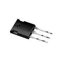
Manufacturer Part Number
SIHG22N60S-E3
Description
MOSFET N-CH 600V 22A TO247
Manufacturer
Vishay
Datasheet
1.SIHG22N60S-E3.pdf
(7 pages)
Specifications of SIHG22N60S-E3
Transistor Polarity
N-Channel
Fet Type
MOSFET N-Channel, Metal Oxide
Fet Feature
Standard
Rds On (max) @ Id, Vgs
190 mOhm @ 22A, 10V
Drain To Source Voltage (vdss)
600V
Current - Continuous Drain (id) @ 25° C
22A
Vgs(th) (max) @ Id
4V @ 250µA
Gate Charge (qg) @ Vgs
75nC @ 10V
Input Capacitance (ciss) @ Vds
2810pF @ 25V
Power - Max
250W
Mounting Type
Through Hole
Package / Case
TO-247-3 (Straight Leads)
Forward Transconductance Gfs (max / Min)
9.4 S
Gate Charge Qg
75 nC
Mounting Style
Through Hole
Resistance Drain-source Rds (on)
0.16 Ohms
Drain-source Breakdown Voltage
600 V
Gate-source Breakdown Voltage
20 V
Continuous Drain Current
22 A
Power Dissipation
250 W
Continuous Drain Current Id
22A
Drain Source Voltage Vds
600V
On Resistance Rds(on)
160mohm
Rds(on) Test Voltage Vgs
10V
Threshold Voltage Vgs Typ
4V
Operating Temperature Range
-55°C To +150°C
Transistor Case Style
TO-247
Rohs Compliant
Yes
Lead Free Status / RoHS Status
Lead free / RoHS Compliant
Lead Free Status / RoHS Status
Lead free / RoHS Compliant, Lead free / RoHS Compliant
Available stocks
Company
Part Number
Manufacturer
Quantity
Price

Part Number:
SIHG22N60S-E3
Manufacturer:
VISHAY/威世
Quantity:
20 000


SiHG22N60S
Vishay Siliconix
Note
a. C
www.vishay.com
2
THE PRODUCT DESCRIBED HEREIN AND THIS DATASHEET ARE SUBJECT TO SPECIFIC DISCLAIMERS, SET FORTH AT
THERMAL RESISTANCE RATINGS
PARAMETER
Maximum Junction-to-Ambient
Maximum Junction-to-Case (Drain)
SPECIFICATIONS (T
PARAMETER
Static
Drain-Source Breakdown Voltage
V
Gate-Source Threshold Voltage (N)
Gate-Source Leakage
Zero Gate Voltage Drain Current
Drain-Source On-State Resistance
Forward Transconductance
Dynamic
Input Capacitance
Output Capacitance
Reverse Transfer Capacitance
Effective Output Capacitance
(Time Related)
Total Gate Charge
Gate-Source Charge
Gate-Drain Charge
Turn-On Delay Time
Rise Time
Turn-Off Delay Time
Fall Time
Gate Input Resistance
Drain-Source Body Diode Characteristics
Continuous Source-Drain Diode Current
Pulsed Diode Forward Current
Diode Forward Voltage
Reverse Recovery Time
Reverse Recovery Charge
Reverse Recovery Current
DS
oss eff.
Temperature Coefficient
(TR) is a fixed capacitance that gives the same charging time as C
a
J
= 25 °C, unless otherwise noted)
TO-247
TO-247
C
This datasheet is subject to change without notice.
SYMBOL
oss eff.
ΔV
R
V
t
t
C
I
I
I
C
C
V
GS(th)
DS(on)
Q
Q
V
d(on)
d(off)
I
RRM
GSS
DSS
g
Q
Q
DS
R
SM
I
t
t
t
DS
oss
SD
rss
S
iss
gd
rr
fs
gs
r
f
g
g
rr
/T
(TR)
J
a
SYMBOL
MOSFET symbol
showing the
integral reverse
p - n junction diode
V
V
R
R
V
V
GS
GS
thJC
GS
thJA
DS
T
Reference to 25 °C, I
= 10 V
= 10 V
J
= 0 V
= 600 V, V
dI/dt = 100 A/μs, V
= 25 °C, I
V
V
V
R
f = 1 MHz, open drain
V
TEST CONDITIONS
V
DS
DS
DD
g
DS
T
GS
= 9.1 Ω, V
J
= 600 V, V
= V
= 380 V, I
V
= 25 °C, I
= 50 V, I
oss
= 0 V, I
f = 1.0 MHz
V
GS
V
DS
GS
GS
S
GS
I
while V
D
= ± 20 V
= 22 A, V
, I
= 25 V,
V
= 0 V,
= 22 A, V
= 0 V, T
TYP.
DS
D
D
GS
-
-
D
= 250 μA
D
= 1 mA
GS
= 0 V to 480 V
F
I
= 13 A
D
= 22 A,
DS
= 10 V
= I
R
D
= 22 A
= 0 V
= 25 V
S
is rising from 0 % to 80 % V
J
GS
= 1 mA
,
DS
= 150 °C
G
= 0 V
= 480 V
D
S
MIN.
600
2.0
MAX.
-
-
-
-
-
-
-
-
-
-
-
-
-
-
-
-
-
-
-
-
-
-
-
-
0.5
62
www.vishay.com/doc?91000
S11-0440-Rev. D, 14-Mar-11
Document Number: 91393
0.160
TYP.
2810
1480
0.70
0.65
155
462
9.4
8.3
33
75
17
25
24
68
77
59
30
DS
-
-
-
-
-
-
-
-
.
MAX.
± 100
0.190
100
4.0
1.2
22
88
1
-
-
-
-
-
-
-
-
-
-
-
-
-
-
-
-
-
-
UNIT
°C/W
UNIT
V/°C
nA
μA
nC
μC
pF
ns
ns
Ω
Ω
V
V
S
A
V
A
Related parts for SIHG22N60S-E3
Image
Part Number
Description
Manufacturer
Datasheet
Request
R

Part Number:
Description:
357-036-542-201 CARDEDGE 36POS DL .156 BLK LOPRO
Manufacturer:
Vishay
Datasheet:
Part Number:
Description:
357-036-542-201 CARDEDGE 36POS DL .156 BLK LOPRO
Manufacturer:
Vishay
Datasheet:
Part Number:
Description:
357-036-542-201 CARDEDGE 36POS DL .156 BLK LOPRO
Manufacturer:
Vishay
Datasheet:
Part Number:
Description:
357-036-542-201 CARDEDGE 36POS DL .156 BLK LOPRO
Manufacturer:
Vishay
Datasheet:
Part Number:
Description:
357-036-542-201 CARDEDGE 36POS DL .156 BLK LOPRO
Manufacturer:
Vishay
Datasheet:
Part Number:
Description:
357-036-542-201 CARDEDGE 36POS DL .156 BLK LOPRO
Manufacturer:
Vishay
Datasheet:
Part Number:
Description:
357-036-542-201 CARDEDGE 36POS DL .156 BLK LOPRO
Manufacturer:
Vishay
Datasheet:
Part Number:
Description:
357-036-542-201 CARDEDGE 36POS DL .156 BLK LOPRO
Manufacturer:
Vishay
Datasheet:
Part Number:
Description:
357-036-542-201 CARDEDGE 36POS DL .156 BLK LOPRO
Manufacturer:
Vishay
Datasheet:
Part Number:
Description:
357-036-542-201 CARDEDGE 36POS DL .156 BLK LOPRO
Manufacturer:
Vishay
Datasheet:
Part Number:
Description:
357-036-542-201 CARDEDGE 36POS DL .156 BLK LOPRO
Manufacturer:
Vishay
Datasheet:
Part Number:
Description:
357-036-542-201 CARDEDGE 36POS DL .156 BLK LOPRO
Manufacturer:
Vishay
Datasheet:
Part Number:
Description:
357-036-542-201 CARDEDGE 36POS DL .156 BLK LOPRO
Manufacturer:
Vishay
Datasheet:
Part Number:
Description:
357-036-542-201 CARDEDGE 36POS DL .156 BLK LOPRO
Manufacturer:
Vishay
Datasheet:
Part Number:
Description:
357-036-542-201 CARDEDGE 36POS DL .156 BLK LOPRO
Manufacturer:
Vishay
Datasheet: