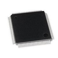
LAN91C96TQFP SMSC, LAN91C96TQFP Datasheet - Page 85

LAN91C96TQFP
Manufacturer Part Number
LAN91C96TQFP
Description
Ethernet ICs Non-PCI 10 Mbps Ethernet MAC
Manufacturer
SMSC
Type
Single Chip MAC and PHY Controllerr
Datasheet
1.LAN91C96-MU.pdf
(125 pages)
Specifications of LAN91C96TQFP
Ethernet Connection Type
10 Base-T, 100 Base-TX
Minimum Operating Temperature
0 C
Mounting Style
SMD/SMT
Product
Ethernet Controllers
Number Of Transceivers
1
Standard Supported
802.3, 802.3u
Data Rate
10 Mbps, 100 Mbps
Supply Voltage (max)
5 V
Supply Voltage (min)
0 V
Supply Current (max)
95 mA
Maximum Operating Temperature
+ 70 C
Package / Case
TQFP-100
Lead Free Status / RoHS Status
Lead free / RoHS Compliant
Non-PCI Single-Chip Full Duplex Ethernet Controller with Magic Packet
Datasheet
9.9
SMSC LAN91C96 5v&3v
For receive, the CPU sets RXEN as a way of starting the CSMA/CD block receive process. The CSMA/CD
block will send data after address filtering through the data path to the DMA block. Data is transferred into
memory as it is received, and the final check on data acceptance is the CRC checking done by the
CSMA/CD block. In any case, the DMA takes care of requesting/releasing memory for receive packets, as
well as generating the byte count.
The receive status word is provided by the CSMA/CD block and written in the first location of the receive
structure by the DMA block. If configured for storing CRC in memory, the CSMA/CD unit will transfer the
CRC bytes through the DMA interface, and then will be treated like regular data bytes.
Note that the receive status word of any packet is available only through memory and is not readable
through any other register. In order to let the CPU know about receive overruns, the RX_OVRN INT is set
and latched in the Interrupt Status Register, which is readable by the CPU at any time.
The address filtering is done inside the CSMA/CD block. A packet will be received if the destination
address is broadcast, or if it is addressed to the individual address of the LAN91C96, or if it is a multicast
address and ALMUL bit is set, or if it is a multicast address matching one of the multicast table entries. If
the PRMS bit is set, all packets are received. The CSMA/CD block is a full duplex machine, and when
working in full duplex mode, the CSMA/CD block will be simultaneously using its data path transmit and
receive interfaces.
Statistical counters are kept by the CSMA/CD block, and are readable through the appropriate register.
The counters are four bits each, and can generate an interrupt when reaching their maximum values.
Software can use that interrupt to update statistics in memory, or it can keep the counter interrupt disabled,
while relying on the transmit interrupt routine reading the counters. Given that the counters can increment
only once per transmit, this technique is a good complement for the single interrupt per sequence strategy.
The interface between the CSMA/CD block and memory is word oriented. Two bi-directional FIFOs make
the data path interface.
Whenever a normal collision occurs (less than 16 retries), the CSMA/CD will trigger the backoff logic and
will indicate the DMA logic of the collision. The DMA is responsible for restarting the data transfer into the
CSMA/CD block regardless of whether the collision happened on the preamble or not.
Only when 16 retries are reached, the CSMA/CD block will clear the TXENA bit, and CPU intervention is
required. The DMA will not automatically restart data transfer in this case, nor will it transmit the next
enqueued packet until TXENA is set by the CPU. The DMA will move the packet number in question from
the TX FIFO into the TX completion FIFO.
Network Interface
The LAN91C96 includes both an AUI interface for thick and thin coax applications and a 10BASE-T
interface for twisted pair applications. Functions common to both are:
1.
2.
3.
4.
5.
Manchester encoder/decoder to convert NRZ data to Manchester encoded data and back.
A 32ms jabber timer to prevent inadvertently long transmissions. When 'jabbing' occurs, the
transmitter is disabled, automatic loopback is disabled (in 10BASE-T mode), and a collision indication
is given to the controller. The interface 'unjabs' when the transmitter has been idle for a minimum of
256 ms.
A phase-lock loop to recover data and clock from the Manchester data stream with up to plus or minus
18ns of jitter.
Diagnostic loopback capability.
LED drivers for collision, transmission, reception, and jabber.
DATASHEET
Page 85
Revision 1.0 (10-24-08)


