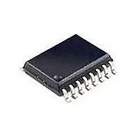
SI2400-BSR Silicon Laboratories Inc, SI2400-BSR Datasheet - Page 78

SI2400-BSR
Manufacturer Part Number
SI2400-BSR
Description
Telecom Line Management ICs CONTACT SILICON LABS FOR AVAILABILITY
Manufacturer
Silicon Laboratories Inc
Type
Integrated Global DAAr
Datasheet
1.SI2400-BS.pdf
(94 pages)
Specifications of SI2400-BSR
Product
Modem Chip
Supply Voltage (min)
3 V
Supply Current
21 mA
Maximum Operating Temperature
+ 85 C
Minimum Operating Temperature
- 40 C
Mounting Style
SMD/SMT
Package / Case
SOIC-16
Lead Free Status / RoHS Status
Lead free / RoHS Compliant
Si2400
A
Introduction
This section describes the detailed functionality of the
integrated DAA included in the Si2400 chipset. This
specific functionality is generally transparent to the user
when using the on-chip controller in the Si2400 modem.
When bypassing the on-chip controller, the low-level
DAA functions of the Si3015 described in this section
can be controlled through S registers.
DAA Isolation Barrier
The Si2400 chipset consists of the Si3015 line-side
device and the Si2400 modem device. The Si2400
achieves an isolation barrier through a low-cost, high-
voltage
Laboratories’ proprietary signal processing techniques.
These techniques eliminate any signal degradation due
to capacitor mismatches, common mode interference,
or noise coupling. As shown in Figure 3 on page 10, the
C1, C4, C24, and C25 capacitors isolate the Si2400
(DSP-side) from the Si3015 (line-side). All transmit,
receive, and control data are communicated through
this barrier.
Emissions/Immunity
The Si2400 chipset and recommended DAA schematic
is fully compliant with and passes all international
electromagnetic emissions and conducted immunity
tests (includes FCC part 15,68; EN50082-1). Careful
attention to the Si2400 bill of materials (page 11),
schematic (Figure 3 on page 10), and layout guidelines
(included in the Si2400URT-EVB data sheet) will ensure
compliance with these international standards. In
designs with difficult layout constraints, the addition of
the C22 and C30 capacitors to the C24 and C25
recommended
performance on emissions and conducted immunity.
Also, under some layout conditions, C22 and C30 may
improve the immunity to telephone line transients. This
is most important for applications that use the voice
codec feature of the Si2400. Because line transients are
infrequent and high voltage in nature, they tend to be
more problematic in voice applications than in data
applications. An occasional pop in a voice application is
quite noticeable, whereas occasional bit errors are
easily corrected in a modem connection with an error-
correction protocol.
78
PPENDIX
capacitor
A—DAA O
capacitors
in
conjunction
may
PERATION
improve
with
modem
Silicon
Rev. 1.3
EN55022 and CISPR-22 Compliance
Compliance to the EN55022:1998 standard will be
necessary to conform to the European Union's EMC
Directive. Adherence to this standard will be necessary
to display the CE mark on designs intended for sale in
the EU. The deadline for EN55022 and CISPR-22
compliance is August 1, 2003. However, some non-
European countries currently require compliance to the
CISPR-22
(Figure 3) and global bill of materials (BOM) (page 11)
contained in this data sheet is designed to be compliant
to the above mentioned standards. It should be noted
that L1, L2, R31, R32, C38, and C39 are only necessary
for those products which are intended for sale in the
European Union or require CISPR-22 compliance. If this
is not the target market then L1 and L2 can be replaced
with 0 Ω resistors and R31, R32, C38, and C39 need
not be populated.
While this population option achieves EN55022 and
CISPR-22 compliance, there are several system
dependent and country dependent issues worth
considering. The first relates to the direct current
resistance (DCR) of the inductors. If the selected
inductors have a DCR of less than 3 Ω each, then
countries which require 300 Ω or less of dc resistance at
TIP and RING with 20 mA of loop current can be
satisfied with the Japan dc termination mode (SF5[3:2]
[DCT] = 01
greater than 3 Ω but less than 8 Ω each, then low
voltage dc termination mode (DCT = 00) must be used
to satisfy the above requirement. In either case, Silicon
Laboratories strongly recommends users of the
ISOmodem adhere to the section “DC Termination
Considerations” for dc termination requirements.
The second consideration relates to the power supply of
the target system. The recommended values for L1, L2,
R31, R32, C38, and C39 assume that the target system
provides a direct current connection between the target
system's reference ground (Si2400 GND) and an
external ground (often the third prong of a power plug).
If there is no direct connection between the reference
ground and external ground, then smaller inductor
values are possible. It should be understood that this
consideration is system dependent, and the impedance
between the system ground and the external ground in
the range of 500 kHz and 10 MHz should be well
known. Please contact a Silicon Laboratories technical
representative for further assistance in analyzing or
testing systems for this consideration.
b
). If the selected inductors have a DCR of
specification.
The
typical
schematic


