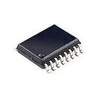
SI2400-BSR Silicon Laboratories Inc, SI2400-BSR Datasheet - Page 59

SI2400-BSR
Manufacturer Part Number
SI2400-BSR
Description
Telecom Line Management ICs CONTACT SILICON LABS FOR AVAILABILITY
Manufacturer
Silicon Laboratories Inc
Type
Integrated Global DAAr
Datasheet
1.SI2400-BS.pdf
(94 pages)
Specifications of SI2400-BSR
Product
Modem Chip
Supply Voltage (min)
3 V
Supply Current
21 mA
Maximum Operating Temperature
+ 85 C
Minimum Operating Temperature
- 40 C
Mounting Style
SMD/SMT
Package / Case
SOIC-16
Lead Free Status / RoHS Status
Lead free / RoHS Compliant
- Current page: 59 of 94
- Download datasheet (2Mb)
S38 (ARM2). Alarm 2 (!7 Mode Only)
Reset settings = 0011_1000
Note: S38 (ALARM2) is used in !7 mode only.
Name
Type
Bit
6:5
4:2
1:0
Bit
7
DBD
R/W
D7
Name
DBD
HMT
DCF
HF
D6
Delay Before Data.
Time the Si2400 waits prior to transmitting data, relative to the end of the handshake
tone.
0 = 300 ms.
1 = Use S2E (RTCT) register contents.
Data Carrier Frequency.
Frequency that the Si2400 will use to transmit.
00 = User programmed. This is accomplished by accessing DSP register 5 prior to using
the !7 command.
01 = 1800 Hz.
10 = 1900 Hz.
11 = 1850 Hz.
Handshake Minimum Time.
The minimum required tone length for a handshake tone or a kissoff tone.
000 = 53 ms.
001 = 160 ms.
010 = 320 ms.
011 = 480 ms.
100 = 640 ms.
101 = 800 ms.
110 = 960 ms.
111 = 1120 ms.
Handshake Frequency.
The frequency that the Si2400 detects as Handshake and Kissoff Tone.
00 = User-defined frequency detectors must be programmed prior to using the !7
command. See DSP Registers.
01 = 1400 Hz only.
10 = 2300 Hz only.
11 = 1400 Hz or 2300 Hz.
DCF
R/W
b
(0x38)
D5
D4
HMT
R/W
D3
Rev. 1.3
D2
Function
D1
R/W
HF
D0
Si2400
59
Related parts for SI2400-BSR
Image
Part Number
Description
Manufacturer
Datasheet
Request
R

Part Number:
Description:
IC ISOMODEM SYSTEM-SIDE 16SOIC
Manufacturer:
Silicon Laboratories Inc
Datasheet:

Part Number:
Description:
2400 BPS ISOMODEM EM SYSTEM-SIDE
Manufacturer:
Silicon Laboratories Inc
Datasheet:

Part Number:
Description:
IC ISOMODEM SYSTEM-SIDE 16SOIC
Manufacturer:
Silicon Laboratories Inc
Datasheet:

Part Number:
Description:
Telecom Line Management ICs 2400b/s System Side
Manufacturer:
Silicon Laboratories Inc
Datasheet:
Part Number:
Description:
SI2400 ISOMODEM LINE-SIDE
Manufacturer:
Silicon Laboratories Inc
Datasheet:
Part Number:
Description:
SMD/C°/SINGLE-ENDED OUTPUT SILICON OSCILLATOR
Manufacturer:
Silicon Laboratories Inc
Part Number:
Description:
Manufacturer:
Silicon Laboratories Inc
Datasheet:
Part Number:
Description:
N/A N/A/SI4010 AES KEYFOB DEMO WITH LCD RX
Manufacturer:
Silicon Laboratories Inc
Datasheet:
Part Number:
Description:
N/A N/A/SI4010 SIMPLIFIED KEY FOB DEMO WITH LED RX
Manufacturer:
Silicon Laboratories Inc
Datasheet:
Part Number:
Description:
N/A/-40 TO 85 OC/EZLINK MODULE; F930/4432 HIGH BAND (REV E/B1)
Manufacturer:
Silicon Laboratories Inc
Part Number:
Description:
EZLink Module; F930/4432 Low Band (rev e/B1)
Manufacturer:
Silicon Laboratories Inc
Part Number:
Description:
I°/4460 10 DBM RADIO TEST CARD 434 MHZ
Manufacturer:
Silicon Laboratories Inc
Part Number:
Description:
I°/4461 14 DBM RADIO TEST CARD 868 MHZ
Manufacturer:
Silicon Laboratories Inc


