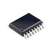
SI2401-FSR Silicon Laboratories Inc, SI2401-FSR Datasheet - Page 41

SI2401-FSR
Manufacturer Part Number
SI2401-FSR
Description
Telecom Line Management ICs 2400b/s System Side 3rd Gen DAA Tech
Manufacturer
Silicon Laboratories Inc
Type
Integrated Global DAAr
Specifications of SI2401-FSR
Product
Modem Module
Supply Voltage (min)
3 V
Supply Current
15 mA
Maximum Operating Temperature
+ 100 C
Minimum Operating Temperature
- 10 C
Mounting Style
SMD/SMT
Package / Case
SOIC-16
Lead Free Status / RoHS Status
Lead free / RoHS Compliant
Available stocks
Company
Part Number
Manufacturer
Quantity
Price
Company:
Part Number:
SI2401-FSR
Manufacturer:
GENNUM
Quantity:
7
Part Number:
SI2401-FSR
Manufacturer:
SILICONLABS/芯科
Quantity:
20 000
S0C (MF2). Modem Functions 2
Reset settings = 0000_0000 (0x00)
Bit
6:5
7
4
3
2
1
0
Name
Type
Bit
CIDM[1:0]
Reserved
Reserved
Name
CDE
MLB
BDL
9BF
CDE
R/W
D7
Carrier Detect Enable.
0 = Disable.
1 = Enable GPI02 as an active low carrier detect pin (must also set SE2[3:2]
[GPIO2] = 01).
Caller ID Monitor.
00 = Caller ID monitor disabled.
01 = Caller ID monitor enabled. Si2401 must detect channel seizure signal followed by
marks in order to report caller ID data. (Normal Bellcore caller ID)
10 = Reserved.
11 = Caller ID monitor enabled. Si2401 must only detect marks in order to report caller ID
data.
Read returns zero.
Ninth Bit Function.
Only valid if the ninth bit escape is set S15[0] (NBE).
0 = Ninth bit equivalent to ALERT.
1 = Ninth bit equivalent to HDLC EOFR.
Blind Dialing.
0 = Blind dialing disabled.
1 = Enables blind dialing after dial timeout register S02 (CW) expires.
Modem Loopback.
0 = Not swapped.
1 = Swaps frequency bands in modem algorithm to do a loopback in a test mode.
Read returns zero.
D6
CIDM[1:0]
R/W
D5
Rev. 1.1
D4
Function
R/W
9BF
D3
BDL
R/W
D2
Si2401/Si3008
MLB
R/W
D1
D0
41


