DMP2012SN-7 Diodes Zetex, DMP2012SN-7 Datasheet
DMP2012SN-7
Specifications of DMP2012SN-7
Available stocks


Related parts for DMP2012SN-7


DMP2012SN-7 Summary of contents
Page 1
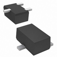
... V SD ⎯ C iss ⎯ C oss ⎯ C rss ⎯ t D(ON) ⎯ t D(OFF) ⎯ ⎯ www.diodes.com DMP2012SN Drain Source TOP VIEW Value Unit -20 V ±12 V -0.7 A -2.8 A Value Unit 500 mW °C/W 250 °C -65 to +150 Typ Max Unit Test Condition ⎯ ⎯ ...
Page 2
... V = - 1. 1.4 1.2 1 0.8 -0.4A 0 -0.7A D 0.4 0.2 0 100 150 - www.diodes.com DMP2012SN V = 10V 25° 125° -55°C J 0.5 1 1 Gate-Source Voltage(V) GS Fig. 2 Typical Transfer Characteristics T = 25° -4. -10V GS 0.5 1 1 DRAIN CURRENT (A) D Fig. 4 On-Resistance vs. Drain Current ...
Page 3
... V , SOURCE-DRAIN VOLTAGE (V) SD Fig. 7 Reverse Drain Current vs. Source-Drain Voltage Ordering Information (Note 6) Part Number DMP2012SN-7 Notes: 6. For packaging details our website at http://www.diodes.com/datasheets/ap02007.pdf. Marking Information Date Code Key Year 2006 Code T Month Jan Feb Code 1 2 Package Outline Dimensions ...
Page 4
... Diodes Incorporated products are not authorized for use as critical components in life support devices or systems without the expressed written approval of the President of Diodes Incorporated. DMP2012SN Document number: DS30790 Rev Dimensions Value (in mm IMPORTANT NOTICE LIFE SUPPORT www.diodes.com DMP2012SN Z 4.0 G 1.2 X 0.9 Y 1 ...