SI1305DL-T1-E3 Vishay, SI1305DL-T1-E3 Datasheet - Page 6
SI1305DL-T1-E3
Manufacturer Part Number
SI1305DL-T1-E3
Description
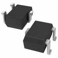
MOSFET P-CH 8V 860MA SOT323-3
Manufacturer
Vishay
Series
TrenchFET®r
Specifications of SI1305DL-T1-E3
Fet Type
MOSFET P-Channel, Metal Oxide
Fet Feature
Logic Level Gate
Rds On (max) @ Id, Vgs
280 mOhm @ 1A, 4.5V
Drain To Source Voltage (vdss)
8V
Current - Continuous Drain (id) @ 25° C
860mA
Vgs(th) (max) @ Id
450mV @ 250µA
Gate Charge (qg) @ Vgs
4nC @ 4.5V
Power - Max
290mW
Mounting Type
Surface Mount
Package / Case
SC-70-3, SOT-323-3
Transistor Polarity
P Channel
Continuous Drain Current Id
-920mA
Drain Source Voltage Vds
-8V
On Resistance Rds(on)
280mohm
Rds(on) Test Voltage Vgs
-4.5V
Threshold Voltage Vgs Typ
-450mV
Lead Free Status / RoHS Status
Lead free / RoHS Compliant
Other names
SI1305DL-T1-E3TR
Available stocks
Company
Part Number
Manufacturer
Quantity
Price
Company:

Part Number:
SI1305DL-T1-E3
Manufacturer:
VISHAY
Quantity:
42 000
Company:
Part Number:
SI1305DL-T1-E3
Manufacturer:
FAIRCHILD
Quantity:
127
Part Number:
SI1305DL-T1-E3
Manufacturer:
VISHAY/威世
Quantity:
20 000


INTRODUCTION
This technical note discusses pin-outs, package outlines, pad
patterns, evaluation board layout, and thermal performance
for single-channel LITTLE FOOT power MOSFETs in the
SC-70 package. These new Vishay Siliconix devices are
intended for small-signal applications where a miniaturized
package is needed and low levels of current (around 350 mA)
need to be switched, either directly or by using a level shift
configuration. Vishay provides these single devices with a
range of on-resistance specifications and in both traditional
3-pin and new 6-pin versions. The new 6-pin SC-70 package
enables improved on-resistance values and enhanced
thermal performance compared to the 3-pin package.
PIN-OUT
Figure 1 shows the pin-out description and Pin 1 identification
for the single-channel SC-70 device in both 3-pin and 6-pin
configurations. The pin-out of the 6-pin device allows the use
of four pins as drain leads, which helps to reduce on-resistance
and junction-to-ambient thermal resistance.
For package dimensions see outline drawings:
SC-70 (3-Leads) (http://www.vishay.com/doc?71153)
SC-70 (6-Leads) (http://www.vishay.com/doc?71154)
Document Number: 71236
12-Dec-03
G
S
Single-Channel LITTLE FOOTR SC-70 3-Pin and 6-Pin MOSFET
1
2
SC-70 (3-LEADS)
ChipFETr
Front of Board SC70-3
SOT-323
Top View
Recommended Pad Pattern and Thermal Peformance
3
FIGURE 1.
D
D
D
G
1
2
3
SC-70 (6-LEADS)
SOT-363
Top View
Back of Board, SC70-3 and SC70-6
vishay.com
FIGURE 2.
6
5
4
BASIC PAD PATTERNS
See Application Note 826, Recommended Minimum Pad
Patterns With Outline Drawing Access for Vishay Siliconix
MOSFETs, (http://www.vishay.com/doc?72286) for the basic
pad layout and dimensions for the 3-pin SC-70 and the 6-pin
SC-70. These pad patterns are sufficient for the low-power
applications for which this package is intended. Increasing the
pad pattern has little effect on thermal resistance for the 3-pin
device, reducing it by only 10% to 15%. But for the 6-pin
device, increasing the pad patterns yields a reduction in
thermal resistance on the order of 35% when using a 1-inch
square with full copper on both sides of the printed circuit board
(PCB). The availability of four drain leads rather than the
traditional single drain lead allows a better thermal path from
the package to the PCB and external environment.
EVALUATION BOARDS FOR THE SINGLE
SC70-3 AND SC70-6
Figure 2 shows the 3-pin and 6-pin SC-70 evaluation boards
(EVB). Both measure 0.6 inches by 0.5 inches. Their copper
pad traces are the same as described in the previous section,
Basic Pad Patterns. Both boards allow interrogation from the
outer pins to 6-pin DIP connections, permitting test sockets to
be used in evaluation testing.
The thermal performance of the single SC-70 has been
measured on the EVB for both the 3-pin and 6-pin devices, the
results shown in Figures 3 and 4. The minimum recommended
footprint on the evaluation board was compared with the
industry standard of 1-inch square FR4 PCB with copper on
both sides of the board.
ChipFETr
Front of Board SC70-6
Vishay Siliconix
www.vishay.com
AN813
1
Related parts for SI1305DL-T1-E3
Image
Part Number
Description
Manufacturer
Datasheet
Request
R


Part Number:
Description:
P-channel 1.8-v G-s Mosfet
Manufacturer:
Vishay
Datasheet:
Part Number:
Description:
P-Ch MOSFET SC-70-3 (SOT-323) 8V 280mohm @ 4.5V
Manufacturer:
Vishay

Part Number:
Description:
P-Channel 1.8-V (G-S) MOSFET
Manufacturer:
VISHAY [Vishay Siliconix]
Datasheet:
Part Number:
Description:
357-036-542-201 CARDEDGE 36POS DL .156 BLK LOPRO
Manufacturer:
Vishay
Datasheet:
Part Number:
Description:
357-036-542-201 CARDEDGE 36POS DL .156 BLK LOPRO
Manufacturer:
Vishay
Datasheet:
Part Number:
Description:
357-036-542-201 CARDEDGE 36POS DL .156 BLK LOPRO
Manufacturer:
Vishay
Datasheet:
Part Number:
Description:
357-036-542-201 CARDEDGE 36POS DL .156 BLK LOPRO
Manufacturer:
Vishay
Datasheet:
Part Number:
Description:
357-036-542-201 CARDEDGE 36POS DL .156 BLK LOPRO
Manufacturer:
Vishay
Datasheet:
Part Number:
Description:
357-036-542-201 CARDEDGE 36POS DL .156 BLK LOPRO
Manufacturer:
Vishay
Datasheet:
Part Number:
Description:
357-036-542-201 CARDEDGE 36POS DL .156 BLK LOPRO
Manufacturer:
Vishay
Datasheet:
Part Number:
Description:
357-036-542-201 CARDEDGE 36POS DL .156 BLK LOPRO
Manufacturer:
Vishay
Datasheet:
Part Number:
Description:
357-036-542-201 CARDEDGE 36POS DL .156 BLK LOPRO
Manufacturer:
Vishay
Datasheet:
Part Number:
Description:
357-036-542-201 CARDEDGE 36POS DL .156 BLK LOPRO
Manufacturer:
Vishay
Datasheet:
Part Number:
Description:
357-036-542-201 CARDEDGE 36POS DL .156 BLK LOPRO
Manufacturer:
Vishay
Datasheet: