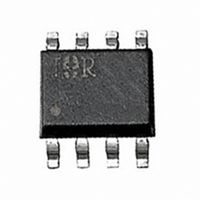
IRF7103Q International Rectifier, IRF7103Q Datasheet - Page 6

IRF7103Q
Manufacturer Part Number
IRF7103Q
Description
MOSFET N-CH 50V 3A 8-SOIC
Manufacturer
International Rectifier
Series
HEXFET®r
Datasheet
1.IRF7103Q.pdf
(10 pages)
Specifications of IRF7103Q
Fet Type
2 N-Channel (Dual)
Fet Feature
Standard
Rds On (max) @ Id, Vgs
130 mOhm @ 3A, 10V
Drain To Source Voltage (vdss)
50V
Current - Continuous Drain (id) @ 25° C
3A
Vgs(th) (max) @ Id
3V @ 250µA
Gate Charge (qg) @ Vgs
15nC @ 10V
Input Capacitance (ciss) @ Vds
255pF @ 25V
Power - Max
2.4W
Mounting Type
Surface Mount
Package / Case
8-SOIC (3.9mm Width)
Transistor Polarity
N Channel
Continuous Drain Current Id
3A
Drain Source Voltage Vds
50V
On Resistance Rds(on)
130mohm
Rds(on) Test Voltage Vgs
10V
Threshold Voltage Vgs Typ
3V
Rohs Compliant
No
Lead Free Status / RoHS Status
Contains lead / RoHS non-compliant
Other names
*IRF7103Q
Available stocks
Company
Part Number
Manufacturer
Quantity
Price
Part Number:
IRF7103QPBF
Manufacturer:
IR
Quantity:
20 000
Part Number:
IRF7103QTRPBF
Manufacturer:
IR
Quantity:
20 000
IRF7103Q
Fig 12. Typical On-Resistance Vs. Gate
6
0.15
0.14
0.13
0.12
0.11
0.10
0.09
2.0
1.8
1.5
1.3
1.0
Fig 14. Typical Threshold Voltage Vs.
-75
4.5
-50
6.0
-V GS, Gate -to -Source Voltage (V)
Junction Temperature
-25
T J , Temperature ( °C )
Voltage
7.5
0
9.0
25
I D = 3.0A
50
10.5
I D = 250µA
75
12.0
100 125
13.5
150
15.0
2.500
2.000
1.500
1.000
0.500
0.000
Fig 13. Typical On-Resistance Vs. Drain
70
60
50
40
30
20
10
0
1.00
0
V GS = 4.5V
5
10
10.00
I D , Drain Current (A)
Typical Power Vs. Time
Current
15
Time (sec)
V GS = 10V
20
100.00
25
www.irf.com
30
35
1000.00
40


