1980-1006 BLUE CHIP TECHNOLOGY, 1980-1006 Datasheet
1980-1006
Manufacturer Part Number
1980-1006
Description
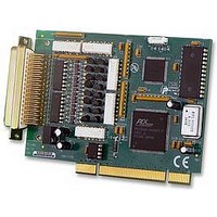
CARD, DATA ACQUISITION, PCI-DIO
Manufacturer
BLUE CHIP TECHNOLOGY
Datasheet
1.1980-1006.pdf
(1 pages)
Specifications of 1980-1006
Interface Type
PCI
Lead Free Status / RoHS Status
Lead free / RoHS Compliant
Datasheet: PCI-DIO
Wide input voltage range suitable for
industrial applications up to 50VDC or peak
AC
3 on-board 16 bit Counter Timers (8254
compatible)
Individually opto-isolated inputs
Opto-isolated outputs
Individually opto-isolated counter timer inputs
and outputs
Software configurable
Supplied with demonstration software
examples
Key Features
32 Channel Isolated Digital Input/Output Card
Certificate No FM 33069
BS EN ISO 9001:2000
The PCI-DIO is a PCI-compatible half-card which provides isolated
digital inputs, outputs and counter/timers.
isolated, current-limited digital inputs available on the board, which
will accept up to 50 volts DC or AC peak, and which switch at
nominally 3.5 volts DC or AC peak.
digital outputs which are isolated from the digital inputs and the host
PC but share a common ground connection. There are also three
programmable counter/timers, the enable and clock inputs being
available, isolated externally, if required , and the outputs being
accessible isolated, externally and as interrupt sources.
A 4Mhz crystal oscillator is available on board to allow the counter/timers to act as accurate timebases. All Input/Output
lines are available at an industry standard 50 way D-type plug connector. One PCI interrupt line may be selectively
driven by the five interrupt sources on the board, the interrupting source being readily identified by software
interrogation of the on-board registers. The five interrupt sources are the three counter \timer outputs and a change of
state detector on each byte of the digital inputs.
Number Of Input Channels
Maximum input voltage
Input Threshold (Vth)
Input current
Input bandwidth
Number Of Output Channels
Maximum ON state current
ON state voltage
Max board output dissipation
Maximum OFF state voltage
Output latency
Maximum Isolation Voltage
Counters/Timers
Onboard Oscillator
Interrupt Sources
Interrupt Levels Supported
Address Overhead
Board Power Requirement
Signal Connections
Dimensions
16
±50 Volt DC or AC peak
2.4 volts minimum. 4.4 volts maximum
1mA ±200mA for Vth < Vin < 50 V DC, +5 mA (max) for -50 V DC < Vin < Vth
10kHz
16
`0mA
1.6 volts (max.) @ Iout = 350mA
2 watts for each group of 8 outputs (Outputs 1 to 8 and 9 to 16)
80 volts DC
2.4 mS max
350 volts DC or AC peak
3 x 16 Bit. Counter/timers 0,1 and 2 may be cascaded to provide a single 48 bit
Counter/timer. All Counter/timers may be clocked externally at a maximum rate of 10 kHz
Frequency 4MHz. Stability ± 100ppm 0 - 70°C
Register selectable to 3 Counter/timer outputs, and 2 input change state detection groups
All PCI interrupts
12 contiguous addresses in 12 byte block
+3.3 Volts, 0.5 W maximum, +5 Volts, 0.4 W maximum
1 x 50 way male ‘D-type’ plug
125 (L) x 91 (H) board only, 135 (L) x 122 (H) x 22 (W) including bracket
There are 16 open collector
There are 16 galvanically
Technical Specification
Blue Chip
1 metre cable with IDC and D type
connector (P/N 1371 0071)
50 way screw terminal adapter
(P/N 1981-0004)
Windows® 98/2000, NT® and
XP® drivers
Technology
Options
Related parts for 1980-1006
Image
Part Number
Description
Manufacturer
Datasheet
Request
R

Part Number:
Description:
CARD, DATA ACQUISITION, PCI-PIO
Manufacturer:
BLUE CHIP TECHNOLOGY
Datasheet:

Part Number:
Description:
CARD, DATA ACQUISITION, PCI-ADC
Manufacturer:
BLUE CHIP TECHNOLOGY
Datasheet:

Part Number:
Description:
ADAPTOR, SCREW TERMINAL, 50WAY
Manufacturer:
BLUE CHIP TECHNOLOGY
Datasheet:

Part Number:
Description:
CARD, ISA, PROG, I/O, 48, CHANNEL
Manufacturer:
BLUE CHIP TECHNOLOGY
Datasheet:

Part Number:
Description:
32 Channel Opto-Isolated Digital Input/Output Card
Manufacturer:
Blue Chip Technology