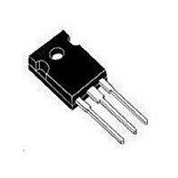
IGW15T120 Infineon Technologies, IGW15T120 Datasheet - Page 2

IGW15T120
Manufacturer Part Number
IGW15T120
Description
IGBT 1200V 30A 110W YO247-3
Manufacturer
Infineon Technologies
Series
TrenchStop™r
Datasheet
1.BUP313.pdf
(12 pages)
Specifications of IGW15T120
Package / Case
TO-247-3 (Straight Leads)
Igbt Type
NPT, Trench and Field Stop
Voltage - Collector Emitter Breakdown (max)
1200V
Vce(on) (max) @ Vge, Ic
2.2V @ 15V, 15A
Current - Collector (ic) (max)
30A
Power - Max
110W
Input Type
Standard
Mounting Type
Through Hole
Configuration
Single
Collector- Emitter Voltage Vceo Max
1200 V
Collector-emitter Saturation Voltage
2.2 V
Maximum Gate Emitter Voltage
+/- 20 V
Continuous Collector Current At 25 C
30 A
Gate-emitter Leakage Current
100 nA
Power Dissipation
110 W
Maximum Operating Temperature
+ 150 C
Continuous Collector Current Ic Max
30 A
Minimum Operating Temperature
- 40 C
Mounting Style
Through Hole
Transistor Type
IGBT
Dc Collector Current
15A
Collector Emitter Voltage Vces
2.2V
Collector Emitter Voltage V(br)ceo
1.2kV
Operating Temperature Range
-40°C To +150°C
Transistor Case Style
TO-247
Rohs Compliant
Yes
Switching Frequency
TRENCHSTOP 2-20kHz
Package
TO-247
Vce (max)
1,200.0 V
Ic(max) @ 25°
30.0 A
Ic(max) @ 100°
15.0 A
Lead Free Status / RoHS Status
Lead free / RoHS Compliant
Lead Free Status / RoHS Status
Lead free / RoHS Compliant, Lead free / RoHS Compliant
Other names
IGW15T120XK
Available stocks
Company
Part Number
Manufacturer
Quantity
Price
Company:
Part Number:
IGW15T120
Manufacturer:
INFINEON
Quantity:
12 500
Part Number:
IGW15T120
Manufacturer:
INFINEON/英飞凌
Quantity:
20 000
Thermal Resistance
Parameter
Characteristic
IGBT thermal resistance,
junction – case
Thermal resistance,
junction – ambient
Electrical Characteristic, at T
Parameter
Static Characteristic
Collector-emitter breakdown voltage
Collector-emitter saturation voltage
Gate-emitter threshold voltage
Zero gate voltage collector current
Gate-emitter leakage current
Transconductance
Integrated gate resistor
Dynamic Characteristic
Input capacitance
Output capacitance
Reverse transfer capacitance
Gate charge
Internal emitter inductance
measured 5mm (0.197 in.) from case
Short circuit collector current
1)
Power Semiconductors
Allowed number of short circuits: <1000; time between short circuits: >1s.
1)
j
= 25 °C, unless otherwise specified
Symbol
R
R
V
V
V
I
I
g
R
C
C
C
Q
L
I
Symbol
C E S
G E S
C ( S C )
f s
E
( B R ) C E S
C E ( s a t )
G E ( t h )
t h J C
t h J A
G i n t
i s s
o s s
r s s
G a t e
TrenchStop
2
V
V
T
T
T
I
V
V
T
T
V
V
V
V
f= 1 M Hz
V
V
V
V
T
C
j
j
j
j
j
j
G E
G E
C E
G E
C E
C E
C E
G E
C C
G E
G E
C C
= 25° C
= 12 5° C
= 15 0° C
= 0. 6mA, V
= 25° C
= 15 0° C
= 25° C
= 1200V
= 0V ,V
= 20V, I
= 25V,
= 0V, I
= 0V
= 0V,
= 9 60V, I
= 1 5V
= 1 5V,t
= 600V,
= 15V, I
Conditions
Conditions
®
Series
C
G E
S C
= 0. 5mA
C
,
C E
= 2 0V
= 15A
C
C
≤10µs
= 15A
= 15A
= V
G E
1200
min.
5.0
-
-
-
-
-
-
-
-
-
-
-
-
-
IGW15T120
Max. Value
Value
none
1100
typ.
100
1.1
1.7
2.0
2.2
5.8
40
10
50
85
13
90
-
-
-
-
Rev. 2.5
max.
100
2.2
6.5
0.2
2.0
-
-
-
-
-
-
-
-
-
-
Nov. 09
Unit
K/W
Unit
V
mA
nA
S
Ω
pF
nC
nH
A


