IXDA20N120AS IXYS, IXDA20N120AS Datasheet
Manufacturer Part Number
IXDA20N120AS
Description
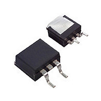
IGBT 1200V 34A TO-263AB
Specifications of IXDA20N120AS
Igbt Type
NPT
Voltage - Collector Emitter Breakdown (max)
1200V
Vce(on) (max) @ Vge, Ic
3.4V @ 15V, 20A
Current - Collector (ic) (max)
34A
Power - Max
200W
Input Type
Standard
Mounting Type
Surface Mount
Package / Case
D²Pak, TO-263 (2 leads + tab)
Channel Type
N
Configuration
Single
Collector-emitter Voltage
1.2kV
Collector Current (dc) (max)
38A
Gate To Emitter Voltage (max)
±20V
Pin Count
2 +Tab
Mounting
Surface Mount
Operating Temperature (min)
-55
Operating Temperature (max)
150C
Operating Temperature Classification
Military
Vces, (v)
1200
Ic25, Tc=25°c, Igbt, (a)
38
Ic90, Tc=90°c, Igbt, (a)
25
Vce(sat), Max, Tj=25°c, Igbt, (v)
3
Tfi, Typ, Igbt, (ns)
70
Eoff, Typ, Tj=125°c, Igbt, (mj)
2.4
Rthjc, Max, Igbt, (°c/w)
0.63
If, Tc=90°c, Diode, (a)
-
Rthjc, Max, Diode, (k/w)
-
Package Style
TO-263 (D2 PAK)
Lead Free Status / RoHS Status
Lead free / RoHS Compliant
Available stocks
Part Number:
IXDA20N120AS
High Voltage IGBT
Short Circuit SOA Capability
Square RBSOA
Preliminary Data
Symbol
V
V
V
V
I
I
I
RBSOA
t
(SCSOA)
P
T
T
Weight
Symbol
V
V
I
I
V
© 2000 IXYS All rights reserved
C25
C90
CM
CES
GES
SC
J
stg
GEM
GE(th)
CE(sat)
CES
CGR
GES
C
(BR)CES
Conditions
T
T
Continuous
Transient
T
T
T
V
Clamped inductive load, L = 30 µH
V
R
T
Conditions
V
I
V
V
I
C
C
J
J
C
C
C
C
GE
GE
GE
CE
CE
G
= 0.6 mA, V
= 20 A, V
= 25°C to 150°C
= 25°C to 150°C; R
= 25°C
= 90°C
= 90°C, t
= 25°C
= 68 W, non repetitive
= ±15 V, T
= ±15 V, V
= 0 V
= V
= 0 V, V
CES
GE
p
GE
= 1 ms
CE
= 15 V
J
= ± 20 V
CE
= 125°C, R
= V
= V
GE
CES
IGBT
T
T
GE
J
J
, T
= 25°C
= 125°C
= 20 kW
J
G
= 125°C
= 68 W
(T
J
= 25°C, unless otherwise specified)
IXDA 20N120 AS
1200
min.
4.5
Characteristic Values
-55 ... +150
-55 ... +150
V
CEK
Maximum Ratings
I
typ.
0.8
2.8
CM
< V
1200
1200
= 35
±20
±30
200
CES
34
21
42
10
2
max.
G
± 500 nA
6.5
0.8 mA
3.4
mA
µs
°C
°C
W
E
C
V
V
V
V
A
A
A
A
g
V
V
V
TO-263 AB
E = Emitter, G = Gate , C (TAB) = Collector
Features
Advantages
Typical Applications
V
I
V
C25
NPT IGBT technology
high switching speed
low tail current
no latch up
short circuit capability
positive temperature coefficient for
easy paralleling
MOS input, voltage controlled
International standard package
Space savings
AC motor speed control
DC servo and robot drives
DC choppers
Uninteruptible power supplies (UPS)
Switch-mode and resonant-mode
power supplies
High power density
CES
CE(sat) typ
G
E
= 1200 V
= 34 A
= 2.8 V
C (TAB)
1 - 4
Related parts for IXDA20N120AS
IXDA20N120AS Summary of contents
... (BR)CES 0.6 mA GE(th CES CE CES ± GES CE(sat © 2000 IXYS All rights reserved IXDA 20N120 AS Maximum Ratings 1200 = 20 kW 1200 GE ±20 ± < V CEK CES , T = 125° 200 -55 ... +150 -55 ... +150 2 Characteristic Values (T = 25°C, unless otherwise specified) J min. typ. max. ...
... res d(on Inductive load d(off ± 600 off R thJC © 2000 IXYS All rights reserved Characteristic Values (T = 25°C, unless otherwise specified) J min. typ. max. 1000 150 CES 125°C J 400 50 3.5 2.1 IXDA 20N120 AS TO-263 0.63 K/W Dim. ...
... T = 25° Fig. 1 Typ. output characteristics 20V 25° Fig. 3 Typ. transfer characteristics 600V 25A Fig. 4 Typ. turn on gate charge © 2000 IXYS All rights reserved V =17V GE 15V 13V I C 11V IXDA 20N120 125° Fig. 2 Typ. output characteristics 125° 1.0 1.5 2 ...
... Fig. 7 Typ. turn on energy and switching times versus gate resistor 125° < V CEK CES 200 400 600 800 1000 1200 Fig. 9 Reverse biased safe operating area RBSOA © 2000 IXYS All rights reserved 140 120 ns E 100 off 600V ±15V 125° 240 ...
Related keywords
- ixda20n120as
- IXDA20N120AS datasheet
- IXDA20N120AS data sheet
- IXDA20N120AS pdf datasheet
- IXDA20N120AS component
- IXDA20N120AS part
- IXDA20N120AS distributor
- IXDA20N120AS RoHS
- IXDA20N120AS datasheet download