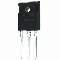
IXGH30N60C3C1 IXYS, IXGH30N60C3C1 Datasheet - Page 7

IXGH30N60C3C1
Manufacturer Part Number
IXGH30N60C3C1
Description
IGBT C3 30A 600V TO-247
Manufacturer
IXYS
Series
GenX3SC™r
Datasheet
1.IXGH30N60C3C1.pdf
(7 pages)
Specifications of IXGH30N60C3C1
Igbt Type
PT
Voltage - Collector Emitter Breakdown (max)
600V
Vce(on) (max) @ Vge, Ic
3V @ 15V, 20A
Current - Collector (ic) (max)
60A
Power - Max
220W
Input Type
Standard
Mounting Type
Through Hole
Package / Case
TO-247
Vces, (v)
600
Ic25, Tc=25°c, Igbt, (a)
60
Ic90, Tc=90°c, Igbt, (a)
-
Ic110, Tc=110°c, Igbt, (a)
30
Vce(sat), Max, Tj=25°c, Igbt, (v)
3
Tfi, Typ, Tj=25°c, Igbt, (ns)
47
Eoff, Typ, Tj=125°c, Igbt, (mj)
0.33
Rthjc, Max, Igbt, (°c/w)
0.56
If, Tj=110°c, Diode, (a)
13
Rthjc, Max, Diode, (ºc/w)
1.1
Package Style
TO-247
Lead Free Status / RoHS Status
Lead free / RoHS Compliant
© 2009 IXYS CORPORATION, All Rights Reserved
10.000
1.000
0.100
0.010
0.001
75
65
55
45
35
25
15
90
80
70
60
50
40
30
20
10
0.00001
25
4
T
V
t
t
R
V
J
CE
r i
G
CE
r i
= 125ºC, V
35
Switching Times vs. Junction Temperature
= 5Ω , V
= 300V
= 300V
6
Switching Times vs. Gate Resistance
45
GE
GE
8
Fig. 18. Inductive Turn-on
= 15V
t
t
Fig. 20. Inductive Turn-on
= 15V
d(on)
d(on)
55
T
- - - -
- - - -
J
10
- Degrees Centigrade
65
R
G
- Ohms
0.0001
75
12
I
85
C
I
= 40A
C
14
= 20A
Fig. 22. Maximum Transient Thermal Impedance for Diode
95
16
I
I
C
C
= 40A
= 20A
105
18
115
0.001
125
20
21
20
19
18
17
16
15
30
28
26
24
22
20
18
16
14
Pulse Width - Second
60
50
40
30
20
10
20
16
12
0
8
4
0
10
0.0
IXGA30N60C3C1 IXGP30N60C3C1
R
V
t
G
CE
r i
= 5Ω , V
= 300V
0.4
0.01
Fig. 21. Forward Current vs. Forward Voltage
Switching Times vs. Collector Current
15
GE
= 15V
0.8
t
Fig. 19. Inductive Turn-on
d(on)
20
- - - -
1.2
I
C
V
25
F
- Amperes
- Volts
T
1.6
J
= 25ºC
IXGH30N60C3C1
T
0.1
J
= 125ºC
2.0
30
2.4
T
T
J
J
35
= 125ºC
IXYS REF: G_30N60C3C1(4D)6-03-09
= 25ºC
2.8
40
24
22
20
18
16
14
12
3.2
1


