IXSH30N60B2D1 IXYS, IXSH30N60B2D1 Datasheet
Home Discrete Semiconductor Products IGBTs - Single IXSH30N60B2D1
Manufacturer Part Number
IXSH30N60B2D1
Description
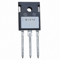
IGBT HS W/DIODE 600V 48A TO247
Specifications of IXSH30N60B2D1
Igbt Type
PT
Voltage - Collector Emitter Breakdown (max)
600V
Vce(on) (max) @ Vge, Ic
2.5V @ 15V, 24A
Current - Collector (ic) (max)
48A
Power - Max
250W
Input Type
Standard
Mounting Type
Through Hole
Package / Case
TO-247
Channel Type
N
Configuration
Single
Collector-emitter Voltage
600V
Collector Current (dc) (max)
48A
Gate To Emitter Voltage (max)
±20V
Package Type
TO-247
Pin Count
3 +Tab
Mounting
Through Hole
Operating Temperature (min)
-55C
Operating Temperature (max)
150C
Operating Temperature Classification
Military
Vces, (v)
600
Ic25, Tc=25°c, Igbt, (a)
48
Ic90, Tc=90°c, Igbt, (a)
-
Vce(sat), Max, Tj=25°c, Igbt, (v)
2
Tfi, Typ, Igbt, (ns)
140
Eoff, Typ, Tj=125°c, Igbt, (mj)
1.18
Rthjc, Max, Igbt, (k/w)
0.5
Package Style
TO-247
Lead Free Status / RoHS Status
Lead free / RoHS Compliant
Available stocks
Part Number:
IXSH30N60B2D1
High Speed IGBT
with Diode
Short Circuit SOA Capability
Preliminary Data Sheet
Symbol
V
V
V
V
I
I
I
I
SSOA
(RBSOA)
t
(SCSOA)
P
T
T
T
Weight
Maximum lead temperature for soldering
1.6 mm (0.062 in.) from case for 10 s
Maximum tab temperature for soldering for 10s
Symbol
V
I
I
V
© 2004 IXYS All rights reserved
C25
C110
F(110)
CM
CES
GES
SC
J
JM
stg
CES
CGR
GES
GEM
C
GE(th)
CE(sat)
Test Conditions
T
T
Continuous
Transient
T
T
T
V
Clamped inductive load
V
R
T
TO-247
TO-268
Test Conditions
I
V
V
V
I
C
C
C
C
C
C
J
J
GE
GE
G
CE
GE
CE
= 10 Ω, non repetitive
= 25°C to 150°C
= 25°C to 150°C; R
= 25°C
= 110°C
= 25°C, 1 ms
= 15 V, T
= 15 V, V
= 25°C
= 750 µA, V
= V
= 0 V
= 0 V, V
= 24A, V
CES
GE
CE
J
GE
= 125°C, R
= ± 20 V
= 360 V, T
= 15 V
CE
= V
GE
GE
= 1 MΩ
G
J
= 125°C
= 10Ω
(T
J
IXSH 30N60B2D1
IXST 30N60B2D1
= 25°C, unless otherwise specified)
min.
4.0
Characteristic Values
-55 ... +150
-55 ... +150
@ 0.8 V
Maximum Ratings
I
typ.
CM
= 48
± 20
± 30
250
300
260
600
600
150
48
30
28
90
CES
10
6
5
± 100
max.
150
7.0
2.5
1
µs
°C
°C
mA
°C
°C
°C
W
µA
nA
V
V
V
V
A
A
A
A
A
g
g
V
V
TO-247 (IXSH)
TO-268 (IXST)
G = Gate
E = Emitter
Features
• International standard package
• Guaranteed Short Circuit SOA
• Low V
• High current handling capability
• MOS Gate turn-on
• Fast fall time for switching speeds
Applications
• AC motor speed control
• Uninterruptible power supplies (UPS)
• Welding
Advantages
• High power density
capability
- for low on-state conduction losses
- drive simplicity
up to 20 kHz
G
V
I
V
C
CE(sat)
C25
E
CES
CE(sat)
G
E
C = Collector
TAB = Collector
= 600 V
= 48 A
= 2.5 V
DS99249(10/04)
C (TAB)
C (TAB)
Related parts for IXSH30N60B2D1
IXSH30N60B2D1 Summary of contents
... Test Conditions = 750 µ GE(th CES CE CES ± GES 24A CE(sat © 2004 IXYS All rights reserved IXSH 30N60B2D1 IXST 30N60B2D1 Maximum Ratings 600 = 1 MΩ 600 GE ± 20 ± 10Ω 0.8 V CES = 125° 250 -55 ... +150 150 -55 ... +150 6 5 300 260 ...
... V = 100 -di/dt = 100 A/µ thJC Note 1: Pulse test, t ≤ 300 µs, duty cycle d ≤ IXYS MOSFETs and IGBTs are covered by 4,835,592 one or moreof the following U.S. patents: 4,850,072 4,881,106 Characteristic Values (T = 25°C, unless otherwise specified) J min. typ. 7.0 12.0 1220 ...
Fig. 1. Output Characteristics º 17V 0.5 1 1 Volts C E Fig. 3. Output Characteristics º @ 125 ...
Fig. 7. Transconductance º - º º 125 Amperes C Fig. 9. Dependence of Turn-Off Energy ...
Fig. 13. Dependence of Turn-off Sw itching Tim e on Tem perature 260 t d(off) 240 48A fi C 24A R = 5Ω G 220 12A V = 15V GE 200 ...
=150° =100° =25° Fig. 18. Forward current I versus V F 2.0 1 1.0 I ...
Related keywords
ixsh30n60 ixsh30n60c ixsh30n60u1 ixsh30n60bd1 ixsh30n60au1 ixsh30n60a IXSH30N60B2D1 datasheet IXSH30N60B2D1 data sheet IXSH30N60B2D1 pdf datasheet IXSH30N60B2D1 component IXSH30N60B2D1 part IXSH30N60B2D1 distributor IXSH30N60B2D1 RoHS IXSH30N60B2D1 datasheet download