STPS140U STMicroelectronics, STPS140U Datasheet
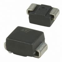
DIODE SCHOTTKY 40V 1A SMB

STPS140U

Manufacturer Part Number
STPS140U
Description
DIODE SCHOTTKY 40V 1A SMB
Manufacturer
STMicroelectronics
Datasheet

Specifications of STPS140U

Voltage - Forward (vf) (max) @ If
550mV @ 1A
Voltage - Dc Reverse (vr) (max)
40V
Current - Average Rectified (io)
1A
Current - Reverse Leakage @ Vr
12µA @ 40V
Diode Type
Schottky
Speed
Fast Recovery =< 500ns, > 200mA (Io)
Mounting Type
Surface Mount
Package / Case
DO-214AA, SMB
Product
Schottky Rectifiers
Peak Reverse Voltage
40 V
Forward Continuous Current
1 A
Max Surge Current
60 A
Configuration
Single
Forward Voltage Drop
0.65 V at 2 A
Maximum Reverse Leakage Current
12 uA
Operating Temperature Range
+ 150 C
Mounting Style
SMD/SMT
Rectifier Type
Schottky Diode
Peak Rep Rev Volt
40V
Avg. Forward Curr (max)
1A
Rev Curr
12uA
Peak Non-repetitive Surge Current (max)
60A
Forward Voltage
0.65V
Operating Temp Range
-65C to 150C
Package Type
SMB
Operating Temperature Classification
Military
Mounting
Surface Mount
Pin Count
2
Lead Free Status / RoHS Status
Lead free / RoHS Compliant
Reverse Recovery Time (trr)
-
Capacitance @ Vr, F
-
Lead Free Status / Rohs Status
Lead free / RoHS Compliant
Other names
497-2490-2

Available stocks

Company
Part Number
Manufacturer
Quantity
Price
Part Number:
STPS140U
Manufacturer:
ST
Quantity:
50 000
Part Number:
STPS140U
Manufacturer:
ST
0
Part Number:
STPS140U
Manufacturer:
ST
Quantity:
20 000
Part Number:
STPS140U /G14
Manufacturer:
ST
0
Part Number:
STPS140U-E
Manufacturer:
ST
0
Part Number:
STPS140U-TR
Manufacturer:
ST
0
Part Number:
STPS140U/G14
Manufacturer:
ST
0
Table 1: Main Product Characteristics
FEATURES AND BENEFITS
DESCRIPTION
Single chip Schottky rectifiers suited to Switched
Mode Power Supplies and high frequency DC to
DC converters.
Packaged in SMA and SMB, this device is
especially intended for surface mounting and used
in low voltage, high frequency inverters, free
wheeling and polarity protection applications.
Table 3: Absolute Ratings (limiting values)
August 2004
* :
Symbol
I
V
F(RMS)
I
P
dV/dt
I
I
I
dPtot
---------------
Very small conduction losses
Negligible switching losses
Low forward voltage drop
Surface mount miniature packages
Avalanche capability specified
F(AV)
T
RRM
FSM
RSM
RRM
ARM
dTj
T
stg
j
>
V
T
------------------------- -
Rth j a
V
j
F
I
F(AV)
(max)
(max)
Repetitive peak reverse voltage
RMS forward voltage
Average forward current
Surge non repetitive forward current
Repetitive peak reverse current
Non repetitive peak reverse current
Repetitive peak avalanche power
Storage temperature range
Maximum operating junction temperature *
Critical rate of rise of reverse voltage
RRM
®
(
1
)
thermal runaway condition for a diode on its own heatsink
150°C
0.5 V
40 V
1 A
Parameter
SMA
SMB
POWER SCHOTTKY RECTIFIER
REV. 8
T
T
tp = 10ms sinusoidal
tp = 2µs F = 1kHz square
tp = 100µs square
tp = 1µs Tj = 25°C
L
L
Table 2: Order Codes
= 130°C δ = 0.5
= 135°C δ = 0.5
(JEDEC DO-214AC)
Part Number
STPS140A
STPS140U
STPS140A
SMA
-65 to + 150
(JEDEC DO-214AA)
STPS140
10000
Value
900
150
40
60
STPS140U
Marking
7
1
1
1
S140
G14
SMB
Unit
V/µs
°C
°C
W
V
A
A
A
A
A
1/7

Related parts for STPS140U

STPS140U Summary of contents

Page 1

... STPS140A STPS140U Parameter = 130°C δ = 0.5 SMA 135°C δ = 0.5 SMB 10ms sinusoidal tp = 2µ 1kHz square tp = 100µs square tp = 1µ 25°C REV. 8 STPS140 SMA SMB (JEDEC DO-214AA) STPS140U Marking S140 G14 Value 900 - 150 150 10000 Unit ...

Page 2

STPS140 Table 4: Thermal Resistance Symbol R Junction to lead th(j-l) Table 5: Static Electrical Characteristics Symbol Parameter I * Reverse leakage current Forward voltage drop F δ Pulse test ms, < 2% ...

Page 3

Figure 5: Non repetitive surge peak forward current versus overload duration (maximum values) (SMA t(s) δ =0.5 0 1E-3 1E-2 Figure 7: Relative variation impedance junction ...

Page 4

STPS140 Figure 11: Forward voltage drop versus forward current (maximum values) I (A) FM 1E+1 T =125°C j 1E+0 1E-1 V (V) FM 1E-2 0.0 0.1 0.2 0.3 0.4 0.5 Figure 13: Thermal resistance junction to ambient versus copper surface ...

Page 5

Figure 14: SMA Package Mechanical Data Figure 15: SMA Foot Print Dimensions (in millimeters) 1.45 2.40 1.45 REF 1.65 STPS140 DIMENSIONS Millimeters Inches Min. ...

Page 6

STPS140 Figure 16: SMB Package Mechanical Data Figure 17: SMB Foot Print Dimensions (in millimeters) 1.52 2.75 6/7 REF 2.3 1.52 DIMENSIONS Millimeters Inches ...

Page 7

... Table 6: Ordering Information Ordering type Marking STPS140A STPS140U ■ Band indicates cathode ■ Epoxy meets UL94, V0 Table 7: Revision History Date Revision Jul-2003 Aug-2004 Information furnished is believed to be accurate and reliable. However, STMicroelectronics assumes no responsibility for the consequences of use of such information nor for any infringement of patents or other rights of third parties which may result from its use. No license is granted by implication or otherwise under any patent or patent rights of STMicroelectronics ...

Related keywords