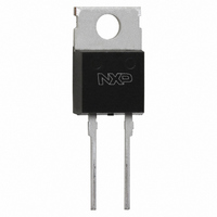
BYC5-600,127 NXP Semiconductors, BYC5-600,127 Datasheet - Page 3

BYC5-600,127
Manufacturer Part Number
BYC5-600,127
Description
DIODE RECT UFAST 600V TO-220AC
Manufacturer
NXP Semiconductors
Datasheet
1.BYC5-600127.pdf
(6 pages)
Specifications of BYC5-600,127
Package / Case
TO-220AC-2
Voltage - Forward (vf) (max) @ If
2.9V @ 5A
Voltage - Dc Reverse (vr) (max)
500V
Current - Average Rectified (io)
5A
Current - Reverse Leakage @ Vr
100µA @ 600V
Diode Type
Standard
Speed
Fast Recovery =< 500ns, > 200mA (Io)
Reverse Recovery Time (trr)
50ns
Mounting Type
Through Hole
Product
Ultra Fast Recovery Rectifier
Configuration
Single
Reverse Voltage
600 V
Forward Voltage Drop
2.9 V
Recovery Time
50 ns
Forward Continuous Current
5 A
Max Surge Current
44 A
Reverse Current Ir
100 uA
Mounting Style
Through Hole
Maximum Operating Temperature
+ 150 C
Minimum Operating Temperature
- 40 C
Lead Free Status / RoHS Status
Lead free / RoHS Compliant
Capacitance @ Vr, F
-
Lead Free Status / Rohs Status
Lead free / RoHS Compliant
Other names
568-3429-5
934054749127
BYC5-600
934054749127
BYC5-600
Philips Semiconductors
March 2001
Rectifier diode
ultrafast, low switching loss
diode, as a function of rate of change of current dI
reverse recovery of diode, as a function of of change
Fig.3. Maximum forward dissipation as a function of
15
10
Fig.4. Typical reverse recovery switching losses in
5
4
3
2
1
0
Fig.5. Typical switching losses in transistor due to
0.15
0.05
5
0
100
0.2
0.1
0
Forward dissipation, PF (W)
Transistor losses due to diode reverse recovery, Ptsw (W)
0
VR = 400 V
Rs = 0.09 Ohms
100
Vo = 1.3 V
average forward current; rectangular current
Tj = 125 C
f = 20 kHz
BYC5-600
Diode reverse recovery switching losses, Pdsw (W)
VR = 400 V
IF = 5 A
Tj = 125 C
f = 20 kHz
BYC5-600
7.5 A
1
waveform where I
Rate of change of current, dIF/dt (A/us)
Rate of change of current, dIF/dt (A/us)
10 A
Average forward current, IF(AV) (A)
2
0.1
of current dI
10 A
3
0.2
IF = 5 A
7.5 A
4
BYC5-600
F(AV)
I
F
5
=I
/dt.
0.5
F(RMS)
t
p
T
6
D = 1.0
x D.
Tmb(max) C
D =
7
t
T
p
t
8
1000
1000
112.5
125
137.5
150
F
/dt.
3
Fig.8. Typical peak reverse recovery current, I
Fig.7. Typical reverse recovery time t
Fig.6. Origin of switching losses in transistor due to
100
100
10
10
1
100
100
function of rate of change of current dI
Reverse recovery time, trr (ns)
Peak reverse recovery current, Irrm (A)
Tj = 125 C
VR = 400 V
Tj = 125 C
VR = 400 V
of rate of change of current dI
VD
ID
Rate of change of current, dIF/dt (A/us)
Rate of change of current, dIF/dt (A/us)
dIF/dt
diode reverse recovery.
IF = 5 A
10 A
10 A
IF = 5 A
Irrm
losses due to
diode reverse recovery
time
ID = IL
7.5 A
Product specification
rr
, as a function
BYC5-600
F
/dt.
BYC5-600
BYC5-600
F
Rev 1.400
/dt.
rrm
1000
1000
as a


