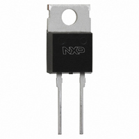
BYC10-600,127 NXP Semiconductors, BYC10-600,127 Datasheet - Page 2

BYC10-600,127
Manufacturer Part Number
BYC10-600,127
Description
DIODE RECT 600V 10A SOT78
Manufacturer
NXP Semiconductors
Datasheet
1.BYC10-600127.pdf
(6 pages)
Specifications of BYC10-600,127
Package / Case
TO-220AC-2
Voltage - Forward (vf) (max) @ If
2.9V @ 10A
Voltage - Dc Reverse (vr) (max)
500V
Current - Average Rectified (io)
10A
Current - Reverse Leakage @ Vr
200µA @ 600V
Diode Type
Standard
Speed
Fast Recovery =< 500ns, > 200mA (Io)
Reverse Recovery Time (trr)
55ns
Mounting Type
Through Hole
Product
Ultra Fast Recovery Rectifier
Configuration
Single
Reverse Voltage
600 V
Forward Voltage Drop
2.9 V at 0.01 A
Recovery Time
55 ns
Forward Continuous Current
10 A
Max Surge Current
71 A
Reverse Current Ir
200 uA
Mounting Style
Through Hole
Maximum Operating Temperature
+ 150 C
Minimum Operating Temperature
- 40 C
Lead Free Status / RoHS Status
Lead free / RoHS Compliant
Capacitance @ Vr, F
-
Lead Free Status / Rohs Status
Lead free / RoHS Compliant
Other names
934054753127
BYC10-600
BYC10-600
BYC10-600
BYC10-600
Philips Semiconductors
ELECTRICAL CHARACTERISTICS
T
March 2001
Rectifier diode
ultrafast, low switching loss
conduction, mode where the transistor turns on whilst
j
SYMBOL PARAMETER
V
I
t
t
t
I
I
V
R
rr
rr
rr
rrm
rrm
converter power factor correction circuit. Continuous
= 25 ˚C unless otherwise stated
F
fr
Fig.1. Typical application, output rectifier in boost
Vin
forward current is still flowing in the diode.
Forward voltage
Reverse current
Reverse recovery time
Reverse recovery time
Reverse recovery time
Peak reverse recovery current
Peak reverse recovery current
Forward recovery voltage
150 uH
typ
IL
500 V MOSFET
ID
OUTPUT DIODE
Vo = 400 V d.c.
CONDITIONS
I
I
I
V
V
I
I
dI
I
dI
I
dI
I
dI
I
F
F
F
F
F
F
F
F
F
R
R
F
F
F
F
= 10 A; T
= 20 A; T
= 10 A;
= 1 A; V
= 10 A; V
= 10 A; V
= 10 A; V
= 10 A; V
= 10 A; dI
/dt = 500 A/ s
/dt = 500 A/ s; T
/dt = 100 A/ s; T
/dt = 500 A/ s; T
= 600 V
= 500 V; T
R
2
j
j
R
R
R
R
= 30 V; dI
F
= 150˚C
= 150˚C
/dt = 100 A/ s
= 400 V;
= 400 V;
= 400 V;
= 400 V;
j
bridge converter. Continuous conduction mode, where
= 100 ˚C
Fig.2. Typical application, freewheeling diode in half
each transistor turns on whilst forward current is still
j
j
j
Vin Vin = 400 V d.c.
= 100˚C
= 125˚C
= 125˚C
F
/dt = 50 A/ s
flowing in the other bridge leg diode.
MIN.
-
-
-
-
-
-
-
-
-
-
-
TYP.
1.4
1.7
2.0
1.1
9.5
35
19
32
9
3
8
Product specification
IL
BYC10-600
inductive load
MAX.
IR
200
1.8
2.3
2.9
3.0
7.5
55
40
12
11
-
IF
Rev 1.400
UNIT
mA
ns
ns
ns
V
V
V
A
A
V
A


