P7SA-14P Omron, P7SA-14P Datasheet - Page 5
P7SA-14P
Manufacturer Part Number
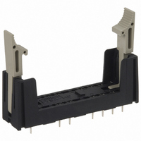
P7SA-14P
Description
G7SA SOCKET, 6 POLE, PWB
Manufacturer
Omron
Series
G7SAr
Type
Socketr
Datasheet
1.G7SA-4A2B_DC24.pdf
(7 pages)
Specifications of P7SA-14P
Number Of Positions
14
Mounting Type
Through Hole
Termination Style
PC Pin
Associated Relay Series
G7SA
Number Of Poles
6
Accessory Type
Sockets
Lead Free Status / RoHS Status
Lead free / RoHS Compliant
For Use With/related Products
G7SA Series
For Use With
Z2944 - RELAY SAFETY PCB 5PST-NO/1NC 24VZ2625 - RELAY SAFETY PCB 3PST-NO 3NCZ2626 - RELAY SAFETY PCB 4PST-NO/2NC 24V
Lead Free Status / Rohs Status
Lead free / RoHS Compliant
Other names
P7SA14P
Z2628
Z2628
Available stocks
Company
Part Number
Manufacturer
Quantity
Price
Company:

Part Number:
P7SA-14P
Manufacturer:
Omron Electronics Inc-EMC Div
Quantity:
135


Certified Standards
G7SA
Back-mounting Socket (for PCB)
P7SA-10P
Back-mounting Socket (for PCB)
P7SA-14P
• EN Standards, VDE Certified
• UL standard UL508 Industrial Control Devices
• CSA standard CSA C22.2 No. 14 Industrial Control Devices
EN61810-1 (Electromechanical non-specified time all-or-nothing
relays)
EN50205 (Relays with forcibly guided (linked) contacts)
0.5
(11.1)
4.1
24.8
60 max.
0.5
(11.1)
49.9
4.1
0.4
24.8
50 max.
(11.1)
39.9
15 max.
Three, 2.6 dia.
(for M3 tapping screws)
0.5
41.5 max.
3.5
0.4
(11.1)
15 max.
Three, 2.6 dia.
(for M3 tapping screws)
0.5
41.5 max.
3.5
G7SA-5A1B Mounted
G7SA-4A2B Mounted
G7SA-3A3B Mounted
Terminal Arrangement/Internal
Connection Diagram
(Bottom View)
0
1
0
1
0
1
Terminal Arrangement/Internal
Connection Diagram
(Bottom View)
11
23
21
21
11
11
12
G7SA-3A1B Mounted
24
12
22
12
22
G7SA-2A2B Mounted
0
1
0
1
33
43
33
43
31
43
34
44
34
44
32
44
Forcibly Guided Contacts
If an NO contact becomes welded, all NC contacts will maintain a
minimum distance of 0.5 mm when the coil is not energized. Likewise
if an NC contact becomes welded, all NO contacts will maintain a
minimum distance of 0.5 mm when the coil is energized.
11
23
21
11
53
63
53
63
53
63
12
24
12
22
54
54
54
64
64
64
33
43
33
43
34
44
34
44
Note: Terminals 23-24, 33-34, 43-44,
Mounting Hole Placement
(Bottom View)
(±0.1 tolerance)
Mounting Hole Placement
(Bottom View)
(±0.1 tolerance)
53-54, and 63-64 are normally
open. Terminals 11-12, 21-22,
and 31-32 are normally closed.
Note: Terminals 23-24, 33-34, and 43-44
are normally open. Terminals 11-12
and 21-22 are normally closed.
Fourteen,
1.1 dia.
Three, 3.2 dia.
(for M3 tapping
screws)
Ten, 1.1 dia.
Three, 3.2 dia.
(for M3 tapping screws)
(from EN50205)
G7SA
5
Related parts for P7SA-14P
Image
Part Number
Description
Manufacturer
Datasheet
Request
R

Part Number:
Description:
SOCKET RELAY 6P DIN MOUNT G7SA
Manufacturer:
Omron
Datasheet:

Part Number:
Description:
Relay Sockets & Hardware 4-P PCB MT SCKT G7SA
Manufacturer:
Omron
Datasheet:
Part Number:
Description:
Contact OSTI For Purchase
Manufacturer:
Omron
Datasheet:

Part Number:
Description:
Contact OSTI For Purchase
Manufacturer:
Omron
Datasheet:
Part Number:
Description:
Contact OSTI For Purchase
Manufacturer:
Omron
Datasheet:

Part Number:
Description:
Contact OSTI
Manufacturer:
Omron
Datasheet:

Part Number:
Description:
G6S-2GLow Signal Relay
Manufacturer:
Omron Corporation
Datasheet:
Part Number:
Description:
Compact, Low-cost, SSR Switching 5 to 20 A
Manufacturer:
Omron Corporation
Datasheet:
Part Number:
Description:
Manufacturer:
Omron Corporation
Datasheet:
Part Number:
Description:
Manufacturer:
Omron Corporation
Datasheet: