P7SA-10F Omron, P7SA-10F Datasheet
P7SA-10F
Specifications of P7SA-10F
Z2947
Available stocks


Related parts for P7SA-10F


P7SA-10F Summary of contents
Page 1
... Rated voltage Model 24 VDC G7SA-3A1B G7SA-2A2B G7SA-5A1B G7SA-4A2B G7SA-3A3B Poles Rated voltage Model 4 poles --- P7SA-10F 6 poles P7SA-14F 4 poles 24 VDC P7SA-10F-ND 6 poles P7SA-14F-ND 4 poles --- P7SA-10P 6 poles P7SA-14P Max. voltage Power consumption 110% (V) 4 poles: Approx. 360 mW 6 poles: Approx. 500 mW G7SA G-3 ...
Page 2
... P7SA-14 (See note 1.) Note the P7SA-1@F is used between 55 and 85 C, reduce the continuous current (from 0.1 A for every degree. 2. Measurement conditions: Measurement of the same points as for the dielectric strength at 500 VDC. 3. When using the P7SA-1@F- VDC, use at an ambient operating temperature from ...
Page 3
Dimensions Note: All units are in millimeters unless otherwise indicated. The diagrams are drawn in perspective. ■ Relays with Forcibly Guided Contacts G7SA-3A1B G7SA-2A2B 40 max. 0.5 G7SA-5A1B G7SA-4A2B G7SA-3A3B 50 max. G-6 Relays with Forcibly Guided Contacts Terminal Arrangement/ ...
Page 4
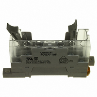
... Sockets Track-mounting Socket P7SA-10F, P7SA-10F-ND 22.5 max. Ten max. 72 max. LED indicator 9 max. 4 dia. Note: The socket is shown with the finger cover removed. Note: Only the -ND Sockets have LED indicators (orange) Track-mounting Socket P7SA-14F, P7SA-14F-ND 30 max. Fourteen max. 72 max. LED indicator 9 max ...
Page 5
... P7SA-10P Back-mounting Socket (for PCB) 50 max. P7SA-14P Back-mounting Socket (for PCB) 60 max. 15 max. 41.5 max. Three, 2.6 dia. (for M3 tapping screws) G-8 Relays with Forcibly Guided Contacts Terminal Arrangement/Internal Connection Diagram 15 max. (Bottom View) G7SA-3A1B Mounted 41.5 max. G7SA-2A2B Mounted Three, 2.6 dia. ...
Page 6
... Precautions for Correct Use !CAUTION Do not touch the terminal area of the Relays or the socket terminal area (charged area) while power is ON. Electric shock will result. Wiring Use one of the following wires to connect to the P7SA-10F/10F-ND/ 14F/14F-ND. 2 Stranded wire: 0. Solid wire: 1 ...
Page 7
... Cancellation; Etc. Orders are not subject to rescheduling or cancellation unless Buyer indemnifies Omron against all related costs or expenses. 10. Force Majeure. Omron shall not be liable for any delay or failure in delivery resulting from causes beyond its control, including earthquakes, fires, floods, strikes or other labor disputes, shortage of labor or materials, accidents to machinery, acts of sabotage, riots, delay in or lack of transportation or the requirements of any government authority ...
Page 8
Cat. No. GC SAFETY-3A 07/05-11/06 Specifications subject to change without notice Printed in USA ...