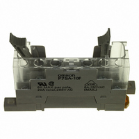
P7SA-10F Omron, P7SA-10F Datasheet - Page 2

P7SA-10F
Manufacturer Part Number
P7SA-10F
Description
Contact OSTI For Purchase
Manufacturer
Omron
Series
G7SAr
Type
Socketr
Specifications of P7SA-10F
Number Of Positions
10
Mounting Type
DIN Rail
Termination Style
Screw Terminal
Associated Relay Series
G7SA
Number Of Poles
4
Accessory Type
Sockets
Lead Free Status / RoHS Status
Lead free / RoHS Compliant
For Use With/related Products
G7SA Series
For Use With
Z2943 - RELAY SAFETY PCB 3PST-NO/1NC 24V
Lead Free Status / Rohs Status
Lead free / RoHS Compliant
Other names
P7SA10F
Z2947
Z2947
Available stocks
Company
Part Number
Manufacturer
Quantity
Price
Company:
Part Number:
P7SA-10F
Manufacturer:
Omron Electronics Inc-EMC Div
Quantity:
135
Specifications
Contacts
■ Characteristics
Sockets
Note: 1. If the P7SA-1@F is used between 55 and 85 C, reduce the continuous current (from 6 A) by 0.1 A for every degree.
Relays with Forcibly Guided Contacts
Note: 1. The values listed above are initial values.
G-4
Load
Rated load
Rated carry current
Max. switching voltage
Max. switching current
P7SA-14@
Contact resistance (See note 2.)
Operating time (See note 3.)
Response time (See note 4.)
Release time (See note 3.)
Maximum
operating
frequency
Insulation resistance
(See note 5.)
Dielectric strength
(see notes 6, 7)
Vibration resistance
Shock resistance
Durability
(see note 8)
Failure rate (P level) (see note 9)
(reference value)
Ambient temperature (see note 10) Operating: 40 C to 85 C (with no icing or condensation)
Ambient humidity
Weight
2. Measurement conditions: Measurement of the same points as for the dielectric strength at 500 VDC.
3. When using the P7SA-1@F-ND at 24 VDC, use at an ambient operating temperature from 25 to 55 C.
2. The contact resistance was measured with 1 A at 5 VDC using the voltage-drop method.
3. These times were measured at the rated voltage and an ambient temperature of 23 C. Contact bounce time is included.
4. The response time is the time it takes for the normally open contacts to open after the coil voltage is turned OFF. Contact bounce time is
5. The insulation resistance was measured with a 500-VDC megohmmeter at the same locations as the dielectric strength was measured.
6. Pole 3 refers to terminals 31 32 or 33 34, pole 4 refers to terminals 43 44, pole 5 refers to terminals 53 54, and pole 6 refers to terminals
7. When using a P7SA Socket, the dielectric strength between coil contacts/different poles is 2,500 VAC, 50/60 Hz for 1 min.
8. The durability is for an ambient temperature of 15 C to 35 C and an ambient humidity of 25% to 75%.
9. The failure rate is based on an operating frequency of 300 operations/min.
10.When operating at a temperature between 70 C and 85 C, reduce the rated carry current (6 A at 70 C or less) by 0.1 A for each degree
Model
included. Measurement conditions: Rated voltage operation, Ambient temperature: 23 C
63 64.
above 70 C.
Relays with Forcibly Guided Contacts
6 A (See note 1.)
Mechanical
Rated load
Destruction
Malfunction
Mechanical
Electrical
Continuous current
100 m
20 ms max.
10 ms max.
20 ms max.
36,000 operations/hr
1,800 operations/hr
1,000 M
Between coil contacts/different poles (except for poles 3 4 in 4-pole Relays and poles 3 5, 4 6, and 5 6
in 6-pole Relays): 4,000 VAC, 50/60 Hz for 1 min.
Between between poles 3 4 in 4-pole Relays and poles 3 5, 4 6, and 5 6 in 6-pole Relays:
2,500 VAC, 50/60 Hz for 1 min.
Between contacts of same polarity: 1,500 VAC, 50/60 Hz for 1 min.
10 to 55 Hz, 0.75-mm single amplitude (1.5-mm double amplitude)
1,000 m/s
100 m/s
10,000,000 operations min. (at approx. 36,000 operations/hr)
100,000 operations min. (at the rated load and approx. 1,800 operations/hr)
5 VDC, 1 mA
Operating: 5% to 85%RH
4 poles:
6 poles:
2
max.
6 A at 250 VAC, 6 A at 30 VDC
6 A
250 VAC, 125 VDC
6 A
2
min. (at 500 VDC)
Approx. 22 g
Approx. 25 g
2,500 VAC for 1 min. between poles
Resistive load
G7SA
Dielectric strength
1,000 M
min. (See note 2.)
Insulation resistance


