H5CX-AS-N AC100-240 Omron, H5CX-AS-N AC100-240 Datasheet - Page 35
H5CX-AS-N AC100-240
Manufacturer Part Number
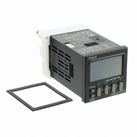
H5CX-AS-N AC100-240
Description
Scrw Term,Trans OUT,Multi-Fnct
Manufacturer
Omron
Series
H5CXr
Specifications of H5CX-AS-N AC100-240
Relay Type
Integrated
Function
Programmable (Multi-Function)
Delay Time
0.001 Sec ~ 9999 Hrs
Output Type
Transistor
Voltage - Supply
100 ~ 240VAC
Mounting Type
Panel Mount
Termination Style
Screw Terminal
Timing Adjustment Method
DIP Switches
Timing Initiate Method
Input Voltage, Trigger Signal
Timing Range
0.001 s to 9999 Hrs
Supply Voltage
100 V to 240 V
Current Rating (max)
100 mA
Display Type
4 Digit LCD Backlight
Product
Digital Timer
Lead Free Status / RoHS Status
Lead free / RoHS Compliant
Circuit
-
Contact Rating @ Voltage
-
Lead Free Status / Rohs Status
Lead free / RoHS Compliant
Other names
H5CXASNAC100240
Z3002
Z3002


Connections
Block Diagram
Terminal Arrangement
(–)
Input Connections
The inputs of the H5CX-B are no-voltage (short-circuit or open) inputs or voltage inputs.
No-voltage Inputs (NPN Inputs)
Open Collector
No-voltage Input Signal Levels
Voltage Inputs (PNP Inputs)
No-contact Input (NPN Transistor)
Voltage Input Signal Levels
Note: 1. The DC voltage must be 30 VDC max.
0 V
No-contact
input
Contact input
High level (Input ON): 4.5 to 30 VDC
Low level (Input OFF): 0 to 2 VDC
6
1
PLC or
sensor
7
2
(+)
2. Input resistance: Approx. 4.7 kΩ
12
8
3
Sensor
OUT 2
Note: Operate with transistor ON
9
4
6
Input circuits
Short-circuit level (Transistor ON)
• Residual voltage: 3 V max.
• Impedance when ON: 1 kΩ max.
Open level (Transistor OFF)
• Impedance when OFF: 100 kΩ min.
Use contacts which can adequately switch 5 mA at 10 V
(Basic insulation)
10
13
5
(The leakage current is approx. 12 mA when the impedance is 0 Ω.)
Output circuit
7
Note: Operate with transistor OFF
6
OUT 1
8
7
9
Note: 1. The power supply and input circuit
8
Internal control
10
9
circuit
2. Terminals 1 and 6 are connected
3. Terminals 7 and 10 have the same
10
are not isolated.
internally.
reset function. The same function will
be performed whichever terminal is
connected. Terminals 7 and 10 are
not connected internally, however, so
do not use them for cross-over wiring.
Voltage Output
Sensor
Power supply
circuit
Display circuit
Key switch
Note: Operate with transistor ON
No-contact Input (PNP Transistor)
circuit
6
7
8
Sensor
9
10
Note: Operate with transistor ON
6
7
Contact Input
Input Circuits
Signal, Reset, and Gate Input
No-voltage Inputs (NPN Inputs)
IN
Transistor Output
8
• The transistor output of
• The diode connected to
the H5CX is insulated
from the internal circuitry
by a photocoupler, so the
transistor output can be
used as both NPN and
PNP output.
the collector of the output
transistor is used to
absorb inverted voltage
that is generated when an
inductive load is
connected to the H5CX.
Note: Operate with relay ON
9
6
10
7
1 kΩ
8
+14 V
9
Internal
circuit
Contact Input
10
• Leakage current:
• Switching capacity: 5 mA min.
• Residual voltage:
• Operating voltage: 10 VDC
NPN Output
DC Two-wire Sensor
Note: Operate with relay ON
Applicable Two-wire Sensor
Power for load
6
Voltage Inputs (PNP Inputs)
IN
Note: Operate with transistor ON
Approx. 4.7 kΩ
7
6
Timer
+
Load
Power for load
1.5 mA max.
3.0 VDC max.
8
7
H5CX-B@-N
9
+
8
PNP Output
10
9
Load
Inductive
load
Power for load
Internal
circuit
10
+
35
Related parts for H5CX-AS-N AC100-240
Image
Part Number
Description
Manufacturer
Datasheet
Request
R

Part Number:
Description:
RELAY TIMER DGTL TRANS 100-240V
Manufacturer:
Omron
Datasheet:

Part Number:
Description:
G6S-2GLow Signal Relay
Manufacturer:
Omron Corporation
Datasheet:
Part Number:
Description:
Compact, Low-cost, SSR Switching 5 to 20 A
Manufacturer:
Omron Corporation
Datasheet:
Part Number:
Description:
Manufacturer:
Omron Corporation
Datasheet:
Part Number:
Description:
Manufacturer:
Omron Corporation
Datasheet:
Part Number:
Description:
Manufacturer:
Omron Corporation
Datasheet:
Part Number:
Description:
Manufacturer:
Omron Corporation
Datasheet:
Part Number:
Description:
Manufacturer:
Omron Corporation
Datasheet:
Part Number:
Description:
Manufacturer:
Omron Corporation
Datasheet: