H3DS-SL AC24-230/DC24-48 Omron, H3DS-SL AC24-230/DC24-48 Datasheet - Page 9
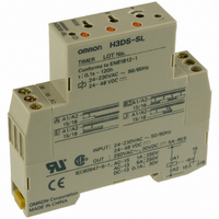
H3DS-SL AC24-230/DC24-48
Manufacturer Part Number
H3DS-SL AC24-230/DC24-48
Description
17.5mm TIMER DIN. MNT.
Manufacturer
Omron
Series
H3DSr
Specifications of H3DS-SL AC24-230/DC24-48
Relay Type
Integrated
Function
Programmable (Multi-Function)
Circuit
SPDT (1 Form C)
Delay Time
0.1 Sec ~ 120 Hrs
Output Type
Mechanical Relay
Contact Rating @ Voltage
5A @ 250VAC
Voltage - Supply
24 ~ 230VAC, 24 ~ 48VDC
Mounting Type
DIN Rail
Termination Style
Screw Terminal
Timing Adjustment Method
Screwdriver Slot
Timing Initiate Method
Input Voltage, Trigger Signal
Timing Range
0.1 s to 120 Hrs
Supply Voltage
24 V to 230 V
Lead Free Status / RoHS Status
Lead free / RoHS Compliant
Lead Free Status / RoHS Status
Lead free / RoHS Compliant
Other names
H3DSSLAC24230DC2448
Z2395
Z2395


■ Timing Chart
Note: 1. The minimum power reset time is 0.1 s and the minimum signal input time is 0.05 s.
Note: The start input of the H3DS-ML@ model is activated by applying a voltage to B1 and A2 terminals.
A: ON-delay
B:
Flicker OFF
start
B2:
Flicker ON
start
C:
Signal
ON/OFF-
delay
Operating
mode
2. The letter “t” in the timing charts stands for the set time and “t–a” means that the period is less than the time set.
3. There is no start input for H3DS-SL@/-AL@ models. Operation starts at power-on.
The voltage can be applied by turning on the contact between B1 and A1 (Refer to Terminal Arrangement).
Power (A
Start (B
(see note)
Output relay: NC
15 and 16
Output relay: NO
(output indicator)
15 and 18
Power indicator
Power (A
Start (B
(see note)
Output relay: NC
15 and 16
Output relay: NO
(output indicator)
15 and 18
Power indicator
Power (A
Start (B
(see note)
Output relay: NC
15 and 16
Output relay: NO
(output indicator)
15 and 18
Power indicator
Power (A
Start (B
(see note)
Output relay: NC
15 and 16
Output relay: NO
(output indicator)
15 and 18
Power indicator
http://www.ia.omron.com/
1
1
1
1
1
1
1
and A
and A
and A
1
and A
and A
and A
and A
and A
2
2
2
2
)
)
)
2
2
2
)
2
)
)
)
)
t
t
t
t
t
t
t–a
t
t–a
t–a
t
t
t
t
t
t–a
t
t
Timing chart
t
t
t–a
(c)Copyright OMRON Corporation 2007 All Rights Reserved.
t–a
t–a
Power
Output
Basic operation
Power
Output
** Start input is invalid while the Timer is in
* For power-on operation, impose voltage to the
Start
* For power-on operation, impose voltage to the
** Start input is invalid while the Timer is in
* Start input is invalid while the Timer is in
Basic operation
Power
Start
Output
*
Basic operation
*
Start
Power
Output
* For power-on operation, impose voltage to the
** Start input is invalid while the Timer is in
Basic operation
Start input. The Timer starts operating at the
moment the power is turned on.
operation.
Start input. The Timer starts operating at the
moment the power is turned on.
operation.
operation.
Start
*
Start input. The Timer starts operating at the
moment the power is turned on.
operation.
**
**
**
t
*
t
t
t
t
t
t
H3DS-M/-S/-A
t
t
t
t
t
t
9
Related parts for H3DS-SL AC24-230/DC24-48
Image
Part Number
Description
Manufacturer
Datasheet
Request
R

Part Number:
Description:
G6S-2GLow Signal Relay
Manufacturer:
Omron Corporation
Datasheet:
Part Number:
Description:
Compact, Low-cost, SSR Switching 5 to 20 A
Manufacturer:
Omron Corporation
Datasheet:
Part Number:
Description:
Manufacturer:
Omron Corporation
Datasheet:
Part Number:
Description:
Manufacturer:
Omron Corporation
Datasheet:
Part Number:
Description:
Manufacturer:
Omron Corporation
Datasheet:
Part Number:
Description:
Manufacturer:
Omron Corporation
Datasheet:
Part Number:
Description:
Manufacturer:
Omron Corporation
Datasheet:
Part Number:
Description:
Manufacturer:
Omron Corporation
Datasheet: