E2C-ED01 Omron, E2C-ED01 Datasheet - Page 14
E2C-ED01
Manufacturer Part Number
E2C-ED01
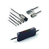
Description
Smart Prox Sensor
Manufacturer
Omron
Series
E2Cr
Specifications of E2C-ED01
Maximum Operating Temperature
+ 60 C
Supply Voltage
12 V to 24 V
Mounting Style
DIN Rail
Sensing Distance
1 mm
Minimum Operating Temperature
- 10 C
Sensor Type
Inductive
Sensing Object
Metallic
Response Frequency
-
Material - Body
Stainless Steel
Shielding
Shielded
Voltage - Supply
-
Output Type
-
Terminal Type
Connector
Package / Case
Cylinder, Threaded
Lead Free Status / Rohs Status
Lead free / RoHS Compliant


PNP Output
Note 1. Setting Areas for Twin-output Models
Nomenclature
Amplifier Units
Twin-output Models
(E2C-EDA11/EDA41/EDA6/EDA8)
14
E2C-EDA41
E2C-EDA8
E2C-EDA51
E2C-EDA9
2. Timing Charts for Timer Settings (T: Set Time)
Sensing
object
Model
Operation Indicator
for Channel 1 (Orange)
ON when output is ON.
OFF when output is OFF.
Normally open: ON between the thresholds for Channel 1 and Channel 2
Normally closed: OFF between the thresholds for Channel 1 and Channel 2
NO
NC
Main Display (Red)
Displays the incident light level
or the function name.
ON delay
OFF
OFF
Yes
ON
ON
No
E2C-EDA
T
Operation mode
NO (Normally
open)
NC (Normally
closed)
NO (Normally
open)
NC (Normally
closed)
T
Operation Indicator
for Channel 2 (Orange)
ON when output is ON.
OFF when output is OFF.
Sub-Display (Green)
Displays the threshold values
and function settings.
High-resolution Digital Proximity Sensor
Sensing
object
Sensing
object
Operation
indicator
(orange)
Output
transistor
Load
(relay, etc.)
Sensing
object
Operation
indicator
(orange)
Output
transistor
Load
(relay, etc.)
Sensing
object
Operation
indicator
(orange)
Output
transistor
Load
(relay, etc.)
Sensing
object
Operation
indicator
(orange)
Output
transistor
Load
(relay, etc.)
NO
NC
SET/RUN Mode Selector
Used to select SET or RUN mode.
OFF delay
(Between blue and black lines)
(Between blue and black lines)
(Between blue and black lines)
(Between blue and black lines)
OFF
OFF
Timing chart
Yes
ON
ON
No
Operate
Operate
Operate
Operate
Not lit
Reset
Not lit
Reset
Not lit
Reset
Not lit
Reset
OFF
OFF
OFF
OFF
Yes
Yes
Yes
Yes
ON
ON
ON
ON
No
No
No
No
Lit
Lit
Lit
Lit
T
Operation Keys
Function setting operations
Channel Selector
Used to select the channel to
display or set.
UP
DOWN
MODE
T
NO
NC
NO
NC
selector
Mode
Sensing
object
NO
NC
One shot
OFF
OFF
Yes
External-input Models
(E2C-EDA21/EDA51/EDA7/EDA9)
ON
ON
No
Operation Indicator
(Orange)
ON when output is ON.
OFF when output is OFF.
Display
Display
Main Display (Red)
Displays the incident light level
or the function name.
T
Operation indicator
(orange) ch1
T
Fine positioning
indicator
(orange)
Proximity
Sensor
main
circuits
Proximity
Sensor
main
circuits
Fine positioning setting
Fine Positioning Indicator
(Orange)
Operation
indicator (orange)
Operation indicator
(orange) ch2
Sub-Display (Green)
Displays the threshold values
and function settings.
Output circuit
SET/RUN Mode Selector
Used to select SET or RUN mode.
Orange
Brown
Blue
Brown
Black
Blue
Black
Orange
output ch2
output ch1
Operation Keys
Function setting operations
Control output
Control
Control
UP
DOWN
MODE
Operating Mode Selector
Used to select normally open
or normally closed.
Load
Load
External
input
Load
12 to 24
VDC
12 to 24
VDC
Related parts for E2C-ED01
Image
Part Number
Description
Manufacturer
Datasheet
Request
R

Part Number:
Description:
DC AMP, M12 E2C-H HiTemp PROX
Manufacturer:
Omron
Datasheet:
Part Number:
Description:
E2C-EDA Shld Flat Sens Head
Manufacturer:
Omron
Datasheet:
Part Number:
Description:
SEP.AMP.PROX. 40MM, 50mm DIST
Manufacturer:
Omron
Datasheet:
Part Number:
Description:
M25, 4MM X 4M CABLE
Manufacturer:
Omron
Datasheet:

Part Number:
Description:
SEP.AMP.PROX. M8 Hi Temp Head
Manufacturer:
Omron
Datasheet:
Part Number:
Description:
SEP.AMP.PROX. M12, 5mm DIST
Manufacturer:
Omron
Datasheet:

Part Number:
Description:
Shld 8mm Smart Box
Manufacturer:
Omron
Datasheet:

Part Number:
Description:
DC AMP NPN FOR E2C PROX
Manufacturer:
Omron
Datasheet:
Part Number:
Description:
DC AMP For M8 E2C-H HiTemp PRX
Manufacturer:
Omron
Datasheet:
Part Number:
Description:
DC AMP, M18 E2C-H HiTemp PROX
Manufacturer:
Omron
Datasheet:
Part Number:
Description:
SEP.AMP.PROX. M18, 10mm DIST
Manufacturer:
Omron
Datasheet: