D4NS-3CF Omron, D4NS-3CF Datasheet
D4NS-3CF
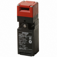
Specifications of D4NS-3CF
Z2733


Related parts for D4NS-3CF


D4NS-3CF Summary of contents
Page 1
... F: 2NC/1NO (MBB contact) 3. Head Mounting Direction F: Four mounting directions possible (Front-side mounting at shipping) Note: An order for the head part or the switch part alone cannot be accepted. The Operation Key is sold separately. D4NS Operation Key D4DS- Operation Key Type 1: Horizontal mounting 2: Vertical mounting ...
Page 2
... M12 connector 2NC 1NC/1NO Model D4NS-1AF (note 3) D4NS-2AF D4NS-3AF D4NS-4AF (note 3) D4NS-1BF (note 3) D4NS-2BF D4NS-3BF D4NS-4BF (note 3) D4NS-1CF (note 3) D4NS-2CF D4NS-3CF D4NS-4CF (note 3) D4NS-1DF D4NS-2DF D4NS-3DF D4NS-4DF (note 3) D4NS-1EF D4NS-2EF D4NS-3EF D4NS-4EF (note 3) D4NS-1FF D4NS-2FF D4NS-3FF D4NS-4FF (note 3) D4NS-5AF D4NS-6AF ...
Page 3
... This fuse is not built into the Switch. UL/CSA (UL508, CSA C22.2 No. 14) A300 Rated Carry current Current voltage Make Break 120 VAC 240 VAC D4NS Model D4DS-K1 D4DS-K2 D4DS-K3 D4DS-K5 File No. B0306 39656052 E76675 File No. Under application DC-13 0.27 A 250 V Volt-amperes ...
Page 4
... The degree of protection is tested using the method specified by the standard (EN60947-5-1). Confirm that sealing properties are suffi- cient for the operating conditions and environment beforehand. Although the switch box is protected from dust or water penetration, do not use the D4NS in places where foreign material may penetrate through the key hole on the head, otherwise Switch damage or mal- functioning may occur. ...
Page 5
... D4NS Head The head can be mounted in four directions. Sealing properties The switch casing ensures IP67 (except the keyhole, which ensures IP00). Use the D4NS in places where the keyhole is free from oil, water, and metal chips. Terminal 11 Terminal 12 Terminal 21 Terminal 31 (33) Terminal 32 (34) ...
Page 6
... Two, 4 depth: 5 2.15±0.05R mounting holes M12 × ± 0.2 14 D4NS-1@F Operating D4NS-2@F characteristics D4NS-3@F D4NS-4@F Key insertion force 15 N max max. Key extraction force Pretravel (PT) 6±3 mm Total travel (TT) (28 mm) Direct opening force 60 N min. dia. holes * 0 Direct opening stroke 10 mm min ...
Page 7
... Black Four, 2.15R 2 10.5 D4DS- Four, 2.15R Black D4NS-1@F + D4DS-K2 Horizontal key insertion radius R ≥ 200 (15) Permissible difference in center lines between the Operation Key and key hole is ±1. Vertical key insertion radius R ≥ 200 (33.5) D4NS-1@F + D4DS-K5 Horizontal key insertion radius R ≥ ...
Page 8
... Do not use metal connector or conduit with this switch. The broken conduit hole may cause electrical shock hazard. Precautions for Safe Use • Be careful not to drop your D4NS, or the switch will not fully exhibit its ability. • Do not disassemble or remodel your D4NS in any case, or the D4NS will not operate normally. • ...
Page 9
... Make sure, however, that the socket connector is tightened securely, otherwise the rated degree of protection of the D4NS may not be maintained. Furthermore, the socket connector may be loosened by vibration. D4NS 8 ...
Page 10
... Production Termination Following the release of the D4NS, production of the D4DS will be terminated. Date of Production Termination Production of the D4DS Series will be terminated in July 2006. Date of Substitute Product Release Sale of the D4NS Series commenced in July 2003. Product Replacement 1. Dimensions The D4DS and D4NS have basically the same structure, and use the same mounting method, Operation Keys, mounting hole and Operation Key insertion positions ...
Page 11
... When transferring devices and equipment, be sure to keep one copy of the Operating Manual and pack another copy with the device or equipment so the person receiving it will have no problem operating it. • Related international standards: ISO/DIS 12100 "Basic concepts, general principles for design" IEC 61508 "Functional safety of electrical/electronic/programmable electronic safety-related systems." D4NS !WARNING G-141 ...
Page 12
ALL DIMENSIONS SHOWN ARE IN MILLIMETERS. To convert millimeters into inches, multiply by 0.03937. To convert grams into ounces, multiply by 0.03527. Cat. No. C128-E2-03-X In the interest of product improvement, specifications are subject to change without notice. G-142 Safety ...