E2C-ED02 Omron, E2C-ED02 Datasheet - Page 9
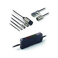
E2C-ED02
Manufacturer Part Number
E2C-ED02
Description
Shld 8mm Smart Box
Manufacturer
Omron
Specifications of E2C-ED02
Maximum Operating Temperature
+ 60 C
Supply Voltage
12 V to 24 V
Mounting Style
DIN Rail
Sensing Distance
2 mm
Minimum Operating Temperature
- 10 C
Lead Free Status / Rohs Status
Lead free / RoHS Compliant


Safety Precautions
Refer to Warranty and Limitations of Liability.
Do not use this product in operating atmospheres or environments
outside the specified ratings.
Amplifier Units
Design
Power ON
The Sensor is ready to sense an object within 200 ms after turning the
power ON. If the load and Sensor are connected to different power
supplies, always turn ON the Sensor power first.
Cable
Use an external power cable of cross-section of 0.3 mm
the Amplifier, and the total length of the cable must be 30 m or less.
Connecting Sensor Heads
Connecting and Disconnecting Sensor Heads
1. Open the protective cover.
2. Making sure that the lock button is up, insert the fibers all the way
To disconnect the Sensor Head, pull out the fibers while pressing on
the lock button.
Do not use this product in any safety device used for the
protection of human lives.
to the back of the Connector insertion opening.
2
Precautions for Correct Use
1
Lock button
WARNING
2
or more for
Connecting and Disconnecting Connectors
<Connecting Connectors>
1. Insert the Master or Slave Connector into the Amplifier Unit until it
2. Apply the supplied seal to the non-connection surface of the
Note: Apply the seal to the grooved side.
<Disconnecting Connectors>
1. Slide the Slave Amplifier Unit.
2. After the Amplifier Unit has been separated, press down on the
Installing and Removing Amplifier Units
<Installing Amplifier Units>
1. Install the Units one by one to the DIN rail.
2. Slide one Unit toward the other, match the clips at the front ends,
<Removing Amplifier Units>
Slide one Unit away from the other and remove them one by one. (Do
not remove the connected Units together from the DIN rail.)
Note: 1. When the Amplifier Units are connected to each other, the
Sensor Head Connector Clips
clicks into place.
Master/Slave Connector.
lever on the Connector and remove it. (Do not attempt to remove
Connectors without separating them from other Amplifier Units
first.)
and then bring them together until they “click.”
2. Before connecting or disconnecting the Units, always
DIN rail
operable ambient temperature changes depending on the
number of connected Amplifier Units. Check
Specifications.
switch power OFF.
Power supply Connector
Protector seal
2
1
2
Insert
Press down.
DIN rail
1
1
Remove
Lever
E2C-EDA
9
Related parts for E2C-ED02
Image
Part Number
Description
Manufacturer
Datasheet
Request
R

Part Number:
Description:
DC AMP, M12 E2C-H HiTemp PROX
Manufacturer:
Omron
Datasheet:
Part Number:
Description:
E2C-EDA Shld Flat Sens Head
Manufacturer:
Omron
Datasheet:
Part Number:
Description:
SEP.AMP.PROX. 40MM, 50mm DIST
Manufacturer:
Omron
Datasheet:

Part Number:
Description:
Smart Prox Sensor
Manufacturer:
Omron
Datasheet:
Part Number:
Description:
M25, 4MM X 4M CABLE
Manufacturer:
Omron
Datasheet:

Part Number:
Description:
SEP.AMP.PROX. M8 Hi Temp Head
Manufacturer:
Omron
Datasheet:
Part Number:
Description:
SEP.AMP.PROX. M12, 5mm DIST
Manufacturer:
Omron
Datasheet:

Part Number:
Description:
DC AMP NPN FOR E2C PROX
Manufacturer:
Omron
Datasheet:
Part Number:
Description:
DC AMP For M8 E2C-H HiTemp PRX
Manufacturer:
Omron
Datasheet:
Part Number:
Description:
DC AMP, M18 E2C-H HiTemp PROX
Manufacturer:
Omron
Datasheet:
Part Number:
Description:
SEP.AMP.PROX. M18, 10mm DIST
Manufacturer:
Omron
Datasheet: