EGP20G-E3/54 Vishay, EGP20G-E3/54 Datasheet - Page 2
EGP20G-E3/54
Manufacturer Part Number
EGP20G-E3/54
Description
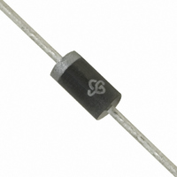
DIODE 2A 400V 50NS DO-204AC
Manufacturer
Vishay
Specifications of EGP20G-E3/54
Voltage - Forward (vf) (max) @ If
1.25V @ 2A
Voltage - Dc Reverse (vr) (max)
400V
Current - Average Rectified (io)
2A
Current - Reverse Leakage @ Vr
5µA @ 400V
Diode Type
Standard
Speed
Fast Recovery =< 500ns, > 200mA (Io)
Reverse Recovery Time (trr)
50ns
Mounting Type
Through Hole
Package / Case
DO-204AC, DO-15, Axial
Product
Fast Recovery Rectifier
Configuration
Single
Reverse Voltage
400 V
Forward Voltage Drop
1.25 V
Recovery Time
50 ns
Forward Continuous Current
2 A @ Ta=55C
Max Surge Current
75 A
Reverse Current Ir
5 uA
Mounting Style
Through Hole
Maximum Operating Temperature
+ 150 C
Minimum Operating Temperature
- 65 C
Lead Free Status / RoHS Status
Lead free / RoHS Compliant
Capacitance @ Vr, F
-
Lead Free Status / Rohs Status
Lead free / RoHS Compliant
Available stocks
Company
Part Number
Manufacturer
Quantity
Price
Company:

Part Number:
EGP20G-E3/54
Manufacturer:
Vishay Semiconductors
Quantity:
4 310
Part Number:
EGP20G-E3/54
Manufacturer:
VISHAY/威世
Quantity:
20 000


EGP20A thru EGP20G
Vishay General Semiconductor
Note:
(1) Thermal resistance from junction to ambient, and from junction to lead at 0.375" (9.5 mm) lead length, P.C.B. mounted
Note:
(1) Automotive grade AEC Q101 qualified
RATINGS AND CHARACTERISTICS CURVES
(T
www.vishay.com
2
ELECTRICAL CHARACTERISTICS (T
PARAMETER
Maximum instantaneous
forward voltage
Maximum DC reverse
current at rated DC
blocking voltage
Maximum reverse
recovery time
Typical junction
capacitance
THERMAL CHARACTERISTICS (T
PARAMETER
Typical thermal resistance
ORDERING INFORMATION (Example)
PREFERRED P/N
EGP20D-E3/54
EGP20D-E3/73
EGP20DHE3/54
EGP20DHE3/73
A
= 25 °C unless otherwise noted)
3.0
2.0
1.0
Figure 1. Maximum Forward Current Derating Curve
0
0
25
(1)
(1)
Ambient Temperature (°C)
50
UNIT WEIGHT (g)
(1)
at 2.0 A
T
T
at I
I
at 4.0 V, 1 MHz
rr
TEST CONDITIONS
A
A
75
= 0.25 A
F
= 25 °C
= 125 °C
Resistive or Inductive Load
0.375" (9.5 mm) Lead Length
= 0.5 A, I
0.452
0.452
0.452
0.452
100
R
125
= 1.0 A,
150
PREFERRED PACKAGE CODE
A
SYMBOL
= 25 °C unless otherwise noted)
SYMBOL
175
A
R
R
V
C
I
t
θJA
θJL
= 25 °C unless otherwise noted)
R
rr
F
J
54
73
54
73
EGP20A
EGP20A
Figure 2. Maximum Non-Repetitive Peak Forward Surge Current
EGP20B EGP20C
EGP20B
90
75
60
45
30
15
0
1
BASE QUANTITY
0.95
70
EGP20C
4000
2000
4000
2000
Number of Cycles at 60 Hz
100
5.0
50
40
15
EGP20D
EGP20D EGP20F
T
8.3 ms Single Half Sine-Wave
J
= T
13" Diameter Paper Tape & Reel
13" Diameter Paper Tape & Reel
10
J
max.
EGP20F
Ammo Pack Packaging
Ammo Pack Packaging
DELIVERY MODE
Document Number: 88583
1.25
45
EGP20G
Revision: 02-Jul-07
EGP20G
100
UNIT
UNIT
°C/W
µA
pF
ns
V
Related parts for EGP20G-E3/54
Image
Part Number
Description
Manufacturer
Datasheet
Request
R

Part Number:
Description:
DIODE 2A 400V 50NS DO-204AC
Manufacturer:
Vishay
Datasheet:

Part Number:
Description:
Rectifiers 400 Volt 2.0A 50ns Glass Passivated
Manufacturer:
Vishay Semiconductors
Datasheet:
Part Number:
Description:
Rectifiers 400 Volt 2.0A 50ns Glass Passivated
Manufacturer:
Vishay Semiconductors
Datasheet:
Part Number:
Description:
Rectifiers 400 Volt 2.0A 50ns Glass Passivated
Manufacturer:
Vishay Semiconductors
Datasheet:
Part Number:
Description:
Rectifiers 2.0 Amp 400 Volt
Manufacturer:
Vishay Semiconductors
Datasheet:

Part Number:
Description:
2.0 Amp Glass Passivated High Efficient Rectifiers 50 to 800 Volts
Manufacturer:
MCC
Datasheet:

Part Number:
Description:
357-036-542-201 CARDEDGE 36POS DL .156 BLK LOPRO
Manufacturer:
Vishay
Datasheet:
Part Number:
Description:
357-036-542-201 CARDEDGE 36POS DL .156 BLK LOPRO
Manufacturer:
Vishay
Datasheet:
Part Number:
Description:
357-036-542-201 CARDEDGE 36POS DL .156 BLK LOPRO
Manufacturer:
Vishay
Datasheet:
Part Number:
Description:
357-036-542-201 CARDEDGE 36POS DL .156 BLK LOPRO
Manufacturer:
Vishay
Datasheet:
Part Number:
Description:
357-036-542-201 CARDEDGE 36POS DL .156 BLK LOPRO
Manufacturer:
Vishay
Datasheet:
Part Number:
Description:
357-036-542-201 CARDEDGE 36POS DL .156 BLK LOPRO
Manufacturer:
Vishay
Datasheet:
Part Number:
Description:
357-036-542-201 CARDEDGE 36POS DL .156 BLK LOPRO
Manufacturer:
Vishay
Datasheet:
Part Number:
Description:
357-036-542-201 CARDEDGE 36POS DL .156 BLK LOPRO
Manufacturer:
Vishay
Datasheet:
Part Number:
Description:
357-036-542-201 CARDEDGE 36POS DL .156 BLK LOPRO
Manufacturer:
Vishay
Datasheet: