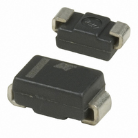
STPS1L60A STMicroelectronics, STPS1L60A Datasheet - Page 4

STPS1L60A
Manufacturer Part Number
STPS1L60A
Description
DIODE SCHOTTKY 60V 1A SMA
Manufacturer
STMicroelectronics
Datasheet
1.STPS1L60A.pdf
(10 pages)
Specifications of STPS1L60A
Voltage - Forward (vf) (max) @ If
570mV @ 1A
Voltage - Dc Reverse (vr) (max)
60V
Current - Average Rectified (io)
1A
Current - Reverse Leakage @ Vr
50µA @ 60V
Diode Type
Schottky
Speed
Fast Recovery =< 500ns, > 200mA (Io)
Mounting Type
Surface Mount
Package / Case
DO-214AC, SMA
Product
Schottky Rectifiers
Peak Reverse Voltage
60 V
Forward Continuous Current
1 A
Max Surge Current
40 A
Configuration
Single
Forward Voltage Drop
0.75 V at 2 A
Maximum Reverse Leakage Current
50 uA
Operating Temperature Range
+ 150 C
Mounting Style
SMD/SMT
Lead Free Status / RoHS Status
Lead free / RoHS Compliant
Reverse Recovery Time (trr)
-
Capacitance @ Vr, F
-
Lead Free Status / Rohs Status
Lead free / RoHS Compliant
Other names
497-2463-2
Available stocks
Company
Part Number
Manufacturer
Quantity
Price
Company:
Part Number:
STPS1L60A
Manufacturer:
STMicroelectronics
Quantity:
55 714
Company:
Part Number:
STPS1L60A
Manufacturer:
TI
Quantity:
5 437
Characteristics
4/10
Figure 7.
Figure 9.
Figure 11. Relative variation of thermal
1.0
0.9
0.8
0.7
0.6
0.5
0.4
0.3
0.2
0.1
0.0
1.E-04
18
16
14
12
10
7
6
5
4
3
2
1
0
1.E-04
1.E-02
8
6
4
2
0
I M (A)
Z th(j-a) /R th(j-a)
I M (A)
I M
I M
Epoxy printed circuit board,
copper thickness = 35 µm,
recommended pad layout
δ = 0.5
δ = 0.5
Single pulse
t
1.E-01
t
Non repetitive surge peak forward
current versus overload duration
(maximum values) (SMA)
Non repetitive surge peak forward
current versus overload duration
(maximum values) (STmite flat)
impedance junction to ambient
versus pulse duration (DO-41)
1.E-03
1.E-03
1.E+00
1.E-02
1.E-02
t(s)
t(s)
1.E+01
1.E-01
1.E-01
1.E+02
STmite flat
T a = 125 °C
T c = 125 °C
T a = 25 °C
T a = 75 °C
T c = 25 °C
T c = 75 °C
SMA
DO-41
t p (s)
Doc ID 7504 Rev 8
1.E+00
1.E+00
1.E+03
Figure 8.
Figure 10. Relative variation of thermal
Figure 12. Relative variation of thermal
1.0
0.9
0.8
0.7
0.6
0.5
0.4
0.3
0.2
0.1
0.0
1.0
0.9
0.8
0.7
0.6
0.5
0.4
0.3
0.2
0.1
0.0
1.E-04
8
7
6
5
4
3
2
1
0
1.E-02
1.E-02
I M (A)
Z th(j-a) /R th(j-a)
Z th(j-a) /R th(j-a)
I M
Epoxy printed circuit board,
copper thickness = 35 µm,
recommended pad layout
Epoxy printed circuit board,
copper thickness = 35 µm,
recommended pad layout
Single pulse
δ = 0.5
Single pulse
1.E-01
1.E-01
t
Non repetitive surge peak forward
current versus overload duration
(maximum values) (DO-41)
impedance junction to ambient
versus pulse duration (SMA)
impedance junction to ambient
versus pulse duration (STmite flat)
1.E-03
1.E+00
1.E+00
1.E-02
t(s)
1.E+01
1.E+01
1.E-01
1.E+02
1.E+02
STmite flat
T a = 25 °C
T a = 125 °C
T a = 75 °C
STPS1L60
DO-41
SMA
t p (s)
t p (s)
1.E+00
1.E+03
1.E+03


