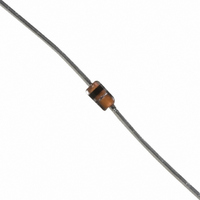
BAT85,113 NXP Semiconductors, BAT85,113 Datasheet - Page 2

BAT85,113
Manufacturer Part Number
BAT85,113
Description
DIODE SCHOTTKY 30V 200MA DO34
Manufacturer
NXP Semiconductors
Datasheet
1.BAT85113.pdf
(8 pages)
Specifications of BAT85,113
Package / Case
DO-204AG, DO-34, Axial
Voltage - Forward (vf) (max) @ If
800mV @ 100mA
Voltage - Dc Reverse (vr) (max)
30V
Current - Average Rectified (io)
200mA (DC)
Current - Reverse Leakage @ Vr
2µA @ 25V
Diode Type
Schottky
Speed
Small Signal =< 200mA (Io), Any Speed
Reverse Recovery Time (trr)
4ns
Capacitance @ Vr, F
10pF @ 1V, 1MHz
Mounting Type
Through Hole
Product
Schottky Diodes
Peak Reverse Voltage
30 V
Forward Continuous Current
0.2 A @ Ta=50C
Max Surge Current
5 A
Configuration
Single
Recovery Time
4 ns
Forward Voltage Drop
0.8 V @ 0.1 A
Maximum Reverse Leakage Current
2 uA @ 25 V
Operating Temperature Range
+ 125 C
Mounting Style
Through Hole
Lead Free Status / RoHS Status
Lead free / RoHS Compliant
Lead Free Status / RoHS Status
Lead free / RoHS Compliant, Lead free / RoHS Compliant
Other names
568-1617-2
933624760113
BAT85 T/R
933624760113
BAT85 T/R
Available stocks
Company
Part Number
Manufacturer
Quantity
Price
Part Number:
BAT85,113
Manufacturer:
NEXPERIA/安世
Quantity:
20 000
NXP Semiconductors
FEATURES
• Low forward voltage
• Guard ring protected
• Hermetically-sealed leaded glass
APPLICATIONS
• Ultra high-speed switching
• Voltage clamping
• Protection circuits
• Blocking diodes.
LIMITING VALUES
In accordance with the Absolute Maximum Rating System (IEC 60134).
2000 May 25
V
I
I
I
I
T
T
T
SYMBOL
F
F(AV)
FRM
FSM
package.
stg
j
amb
R
Schottky barrier diode
continuous reverse voltage
continuous forward current
average forward current
repetitive peak forward current
non-repetitive peak forward current
storage temperature
junction temperature
operating ambient temperature
PARAMETER
DESCRIPTION
Planar Schottky barrier diode with an integrated protection ring against static
discharges, encapsulated in a hermetically-sealed subminiature SOD68
(DO-34) package. The diode is suitable for mounting on a 2 E (5.08 mm) pitch.
Fig.1 Simplified outline (SOD68; DO-34), pin configuration and symbol.
handbook, halfpage
PCB mounting, lead length = 4 mm;
V
T
t
t
p
p
amb
RWM
≤ 1 s; δ 0.5
≤ 10 ms
= 50 °C; see Fig.2
= 25 V; a = 1.57; δ = 0.5;
2
k
CONDITIONS
−
−
−
−
−
−65
−
−65
MIN.
a
Product data sheet
30
200
200
300
5
+150
125
+125
MAX.
MAM193
BAT85
V
mA
mA
mA
A
°C
°C
°C
UNIT


