G6H-2-DC12 Omron, G6H-2-DC12 Datasheet - Page 8
G6H-2-DC12
Manufacturer Part Number
G6H-2-DC12
Description
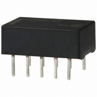
LOW SIGNAL RELAY
Manufacturer
Omron
Series
G6Hr
Type
Signal Relayr
Datasheet
1.G6H-2-DC9.pdf
(10 pages)
Specifications of G6H-2-DC12
Relay Type
Telecom
Circuit
DPDT (2 Form C)
Contact Rating @ Voltage
1A @ 30VDC
Coil Type
Standard
Coil Current
11.7mA
Coil Voltage
12VDC
Control On Voltage (max)
9 VDC
Control Off Voltage (min)
1.2 VDC
Mounting Type
Through Hole
Termination Style
PC Pin
Contact Form
2 Form C
Power Consumption
140 mW
Maximum Switching Current
1 A
Contact Rating
0.50 A at 125 VAC, 1 A at 30 VDC
Relay Construction
Non-Latching
Contact Arrangement
DPDT
Coil Voltage Dc
12V
Voltage Rating (vdc)
110V
Voltage Rating (vac)
125V
Dropout Volt (min)
1.2VDCV
Coil Resistance
1.028kohm
Pick-up Voltage (max)
9VDC
Maximum Power Rating
33W/62.5VA
Operate Time
3ms
Contact Current Rating
1A
Contact Material
Ag/Au Clad
Coil Suppression Diode
No
Push To Test Button
No
Led Indicator
No
Seal
Sealed
Product Height (mm)
5.4mm
Product Depth (mm)
9.3mm
Product Length (mm)
14.3mm
Operating Temp Range
-40C to 70C
Pin Count
10
Mounting Style
Through Hole
Package / Case
DIP
Lead Free Status / RoHS Status
Lead free / RoHS Compliant
Lead Free Status / RoHS Status
Lead free / RoHS Compliant
Other names
G6H2DC12
Z741
Z741
Available stocks
Company
Part Number
Manufacturer
Quantity
Price
Company:

Part Number:
G6H-2-DC12V
Manufacturer:
OMRON
Quantity:
12 000


Precautions
Long-term Continuously ON Contacts
Using the Relay in a circuit where the Relay will be ON continuously
for long periods (without switching) can lead to unstable contacts
because the heat generated by the coil itself will affect the insulation,
causing a film to develop on the contact surfaces. We recommend
using a latching relay (magnetic-holding relay) in this kind of circuit. If
a single-side stable model must be used in this kind of circuit, we rec-
ommend using a fail-safe circuit design that provides protection
against contact failure or coil burnout.
Claw Securing Force During Automatic Mounting
During automatic insertion of Relays, be sure to set the securing
force of each claw to the following so that the Relay’s characteristics
will be maintained.
56
Direction A: 1.96 N max.
Direction B: 4.90 N max.
Direction C: 1.96 N max.
A
C
B
Low Signal Relay
G6H
DISCONTINUED
Relay Handling
Use the Relay as soon as possible after opening the moisture-proof
package. If the Relay is left for a long time after opening the mois-
ture-proof package, the appearance may deteriorate and seal failure
may occur after the solder mounting process. To store the Relay after
opening the moisture-proof package, place it into the original pack-
age and seal the package with adhesive tape.
When washing the product after soldering the Relay to a PCB, use a
water-based solvent or alcohol-based solvent, and keep the solvent
temperature to less than 40°C. Do not put the Relay in a cold clean-
ing bath immediately after soldering.
Related parts for G6H-2-DC12
Image
Part Number
Description
Manufacturer
Datasheet
Request
R

Part Number:
Description:
RELAY LOW SIGNAL
Manufacturer:
Omron
Datasheet:

Part Number:
Description:
LOW SIGNAL RELAY
Manufacturer:
Omron
Datasheet:
Part Number:
Description:
LOW SIGNAL RELAY
Manufacturer:
Omron
Datasheet:

Part Number:
Description:
RELAY DPDT 5VDC 1A SMD
Manufacturer:
Omron
Datasheet:
Part Number:
Description:
RELAY DPDT 12VDC 1A SMD
Manufacturer:
Omron
Datasheet:
Part Number:
Description:
RELAY DPDT 24VDC 1A SMD
Manufacturer:
Omron
Datasheet:
Part Number:
Description:
RELAY LOW SIGNAL
Manufacturer:
Omron
Datasheet:

Part Number:
Description:
Low Signal Relays - PCB 1A Relay PC MNT DPDT 5VDC
Manufacturer:
Omron
Datasheet:
Part Number:
Description:
RELAY MINI PC MNT DPDT 1A 5VDC
Manufacturer:
Omron
Datasheet:
Part Number:
Description:
RELAY MINI PC MNT DPDT 1A 24VDC
Manufacturer:
Omron
Datasheet:

Part Number:
Description:
LOW SIGNAL RELAY
Manufacturer:
Omron
Datasheet:

Part Number:
Description:
G6S-2GLow Signal Relay
Manufacturer:
Omron Corporation
Datasheet:
Part Number:
Description:
Compact, Low-cost, SSR Switching 5 to 20 A
Manufacturer:
Omron Corporation
Datasheet: