G6H-2-DC12 Omron, G6H-2-DC12 Datasheet - Page 3
G6H-2-DC12
Manufacturer Part Number
G6H-2-DC12
Description
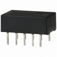
LOW SIGNAL RELAY
Manufacturer
Omron
Series
G6Hr
Type
Signal Relayr
Datasheet
1.G6H-2-DC9.pdf
(10 pages)
Specifications of G6H-2-DC12
Relay Type
Telecom
Circuit
DPDT (2 Form C)
Contact Rating @ Voltage
1A @ 30VDC
Coil Type
Standard
Coil Current
11.7mA
Coil Voltage
12VDC
Control On Voltage (max)
9 VDC
Control Off Voltage (min)
1.2 VDC
Mounting Type
Through Hole
Termination Style
PC Pin
Contact Form
2 Form C
Power Consumption
140 mW
Maximum Switching Current
1 A
Contact Rating
0.50 A at 125 VAC, 1 A at 30 VDC
Relay Construction
Non-Latching
Contact Arrangement
DPDT
Coil Voltage Dc
12V
Voltage Rating (vdc)
110V
Voltage Rating (vac)
125V
Dropout Volt (min)
1.2VDCV
Coil Resistance
1.028kohm
Pick-up Voltage (max)
9VDC
Maximum Power Rating
33W/62.5VA
Operate Time
3ms
Contact Current Rating
1A
Contact Material
Ag/Au Clad
Coil Suppression Diode
No
Push To Test Button
No
Led Indicator
No
Seal
Sealed
Product Height (mm)
5.4mm
Product Depth (mm)
9.3mm
Product Length (mm)
14.3mm
Operating Temp Range
-40C to 70C
Pin Count
10
Mounting Style
Through Hole
Package / Case
DIP
Lead Free Status / RoHS Status
Lead free / RoHS Compliant
Lead Free Status / RoHS Status
Lead free / RoHS Compliant
Other names
G6H2DC12
Z741
Z741
Available stocks
Company
Part Number
Manufacturer
Quantity
Price
Company:

Part Number:
G6H-2-DC12V
Manufacturer:
OMRON
Quantity:
12 000


■ Characteristics
Note: 1. The contact resistance was measured with 10 mA at 1 VDC with a fall-of-potential method.
■ Approvals
UL Recognized (File No. E41515) / CSA Certified (File No. LR31928) - - Ambient Temp. = 40°C
Note: 1. The rated values approved by each of the safety standards (e.g., UL, CSA, TUV) may be different from the performance characteristics
Contact resistance (See note 1)
Operate (set) time (See note 2)
Release (reset) time (See note 2)
Min. set/reset signal width
Operating frequency
(max.)
Insulation resistance (See note 3)
Dielectric strength
Surge withstand voltage
Vibration
Shock
Ambient temperature
Humidity
Service life
Weight
G6H-2(F)
G6HU-2
G6HK-2
2. Values in parentheses are typical values unless otherwise stated.
3. The insulation resistance was measured with a 500-VDC megohmmeter applied to the same parts as those for checking the dielectric strength.
4. The above values are initial values.
2. In the interest of product improvement, specifications are subject to change.
(The insulation resistance between the set and reset coil (G6HK-2), however, is 100MΩ min. when measured with a 125-VDC megohmmeter).
individually defined in this catalog.
Type
Mechanical
Electrical
Mechanical durability 10 to 55 Hz; 5 mm double amplitude
Malfunction durability 10 to 55 Hz; 3 mm double amplitude
Mechanical durability 1,000 m/s
Malfunction durability 500 m/s
Mechanical
Electrical
DPDT
50 mΩ max. (through-hole); 60 mΩ max. (surface mount)
Non-latching: 3 ms max. (approx. 2.0 ms)
Latching: 3ms max. (approx. 1.5 ms)
Non-latching: 2 ms max. (approx. 1.0 ms)
Latching: 3ms max. (approx. 1.5 ms)
5ms min. (at 23°C)
36,000 operations/hour
1,800 operations/hour (under rated load)
1,000 MΩ max. (at 500 VDC)
1,000 VAC, 50/60 Hz for 1 minute between coil and contacts
1,000 VAC, 50/60 Hz for 1 minute between contacts of different poles
750 VAC, 50/60 Hz for 1 minute between contacts of same pole
125 VAC, 50/60 Hz for 1 minute between set and reset coils (G6HK-2)
1,500 V (10 x 160 μs) between contacts of same polarity (conforms to FCC Part 68)
-40° to 70°C with no icing
5% to 85% RH
100 million operations min. (at 36,000 operations/hr)
200,000 operations min. (at 1,800 operations/hr) See “Characteristic Data”
Approx. 1.5 g
Contact form
DISCONTINUED
2
(approx. 50 G)
2
(approx. 100 G)
1.50 to 48 VDC
Coil rating
Low Signal Relay
2 A, 30 VDC
0.30 A, 110 VDC
0.50 A, 125 VAC
Contact ratings
G6H
51
Related parts for G6H-2-DC12
Image
Part Number
Description
Manufacturer
Datasheet
Request
R

Part Number:
Description:
RELAY LOW SIGNAL
Manufacturer:
Omron
Datasheet:

Part Number:
Description:
LOW SIGNAL RELAY
Manufacturer:
Omron
Datasheet:
Part Number:
Description:
LOW SIGNAL RELAY
Manufacturer:
Omron
Datasheet:

Part Number:
Description:
RELAY DPDT 5VDC 1A SMD
Manufacturer:
Omron
Datasheet:
Part Number:
Description:
RELAY DPDT 12VDC 1A SMD
Manufacturer:
Omron
Datasheet:
Part Number:
Description:
RELAY DPDT 24VDC 1A SMD
Manufacturer:
Omron
Datasheet:
Part Number:
Description:
RELAY LOW SIGNAL
Manufacturer:
Omron
Datasheet:

Part Number:
Description:
Low Signal Relays - PCB 1A Relay PC MNT DPDT 5VDC
Manufacturer:
Omron
Datasheet:
Part Number:
Description:
RELAY MINI PC MNT DPDT 1A 5VDC
Manufacturer:
Omron
Datasheet:
Part Number:
Description:
RELAY MINI PC MNT DPDT 1A 24VDC
Manufacturer:
Omron
Datasheet:

Part Number:
Description:
LOW SIGNAL RELAY
Manufacturer:
Omron
Datasheet:

Part Number:
Description:
G6S-2GLow Signal Relay
Manufacturer:
Omron Corporation
Datasheet:
Part Number:
Description:
Compact, Low-cost, SSR Switching 5 to 20 A
Manufacturer:
Omron Corporation
Datasheet: