AP-B Omron, AP-B Datasheet - Page 6
AP-B
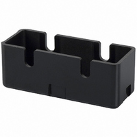
Manufacturer Part Number
AP-B
Description
SWITCH
Manufacturer
Omron
Type
Terminal Coverr
Specifications of AP-B
Accessory Type
Terminal Cover
Features
Phenolic Construction
Illumination
Not Illuminated
Height
20.2 mm
Length
53.8 mm
Mounting Style
Screw
Width
21 mm
Lead Free Status / RoHS Status
Lead free / RoHS Compliant
For Use With
SW234 - SWITCH 20A SHORT ROLLERSW233 - SWITCH 20A PANEL MOUNT PLUNGERSW232 - SWITCH 20A LONG ROLLERSW231 - SWITCH 20A LONG LEVERSW230 - SWITCH 20A PIN PLUNGERSW198 - SWITCH 15A LEVER LOW FORCESW197 - SWITCH 15A SHORT ROLLERSW196 - SWITCH 15A ROLLER LOW FORCESW195 - SWITCH 15A LEVER LOW FORCESW194 - SWITCH 15A PANEL MOUNT ROLLERSW193 - SWITCH 15A PANEL MOUNT ROLLERSW192 - SWITCH 15A PANEL MOUNT PIN PLUNSW191 - SWITCH 15A SPRING PLUNGERSW190 - SWITCH 15A PIN PLUNGER
For Use With/related Products
Omron A/Z Series
Lead Free Status / Rohs Status
Lead free / RoHS Compliant
Other names
APB
SW235
SW235


Specifications
■ Characteristics
*1 The values are for the plunger models. (For the lever models, the values are
*2 The values are for the Z-15G pin plunger.
*3 The values are for the Z-10FY-B.
■ Ratings (Basic, Split-contact and Maintained contact Models)
Z-15 (Except Micro Load and Flexible Rod Models)
* Figures in parentheses are for the Z-15HW52, Z-15HW78(-B) and Z-15H2(-B) models, the AC ratings of these models are 125 and 250 V only.
152
Item
Operating speed
Operating
frequency
Contact resistance
Insulation resistance
Dielectric strength
(50 / 60 Hz for 1 min.)
Vibration
resistance
Shock
resistance
Degree of
protection
Degree of protection
against electric shock
Proof tracking index
(PTI)
Ambient
operating
temperature
Ambient
operating
humidity
Service life
Weight
Contact gap
G, H, H2, E
at the plunger section.)
H, H2
G
E
Mechanical 240 operations/min
Electrical
Malfunction
Destruction 1,000 m/s
Malfunction 300 m/s
General-
purpose
Drip-proof
General-
purpose
Drip-proof
General-
purpose
Drip-proof
Mechanical
Electrical
General-purpose Basic Switch
Classification
125 VAC
250 VAC
500 VAC *
8 VDC
14 VDC
30 VDC
125 VDC
250 VDC
8 VDC
14 VDC
30 VDC
125 VDC
250 VDC
8 VDC
14 VDC
30 VDC
125 VDC
250 VDC
Rated voltage
Item
0.01 mm to 1 m/s (*1)
20 operations/min
15 mΩ max. (initial value) 50 mΩ max. (initial value) 15 mΩ max. (initial value)
100 MΩ min. (at 500 VDC)
Between contacts of same polarity
Contact gap G: 1,000 VAC
Contact gap H: 600 VAC
Contact gap E: 1,500 VAC
Between current-carrying metal parts and ground, and between each terminal and non-current-carrying metal parts:
2,000 VAC
10 to 55 Hz, 1.5-mm double amplitude (*5)
IP00
Equivalent to IP62 (except terminals)
Class I
175
−25°C to 80°C (with no icing)
−15°C to 80°C (with no icing)
35% to 85%RH
35% to 95%RH
Contact gap H2: 10,000,000 operations min.
Contact gap G, H: 20,000,000 operations min.(*4)
Contact gap E: 300,000 operations
Contact gap G, H: 500,000 operations min.
Contact gap E: 100,000 operations min.
Approx. 22 to 58 g
(except micro load
and flexible rod)
2
max. (*2, *5)
Z-15
2
max.
NC
Resistive load
15 (10) *
15 (10) *
0.25
0.75
0.5
0.4
0.2
0.3
10
15
15
15
15
15
15
15
6
2
Non-inductive load (A)
NO
Z
Z-01H
0.25
0.75
NC
2.5
1.5
0.5
0.4
0.2
0.3
3
3
3
3
3
3
2
3
3
3
Lamp load
1 mm to 1 m/s
120 operations/min
Between contacts of same polarity
Contact gap G: 1,000 VAC
Contact gap H: 600 VAC
10 to 20 Hz, 1.5-mm double amplitude (*5) 10 to 55 Hz, 1.5-mm double amplitude (*5)
50 m/s
1,000,000 operations min.
100,000 operations min.
Approx. 42 to 48 g
*4 The values are for the pin plunger. The service life for models other than the
*5 Malfunction: 1 ms max.
2
max. (*5)
1.25
0.75
0.25
0.75
NO
1.5
1.5
1.5
1.5
0.5
1.5
1.5
1.4
0.4
0.2
1.5
1.5
1.5
0.3
pin plunger is 10,000,000 min.
(flexible rod)
Z-15
NC
Inductive load
15 (10)
15 (10)
0.05
0.03
0.03
0.02
0.4
0.2
15
10
15
10
15
15
10
6
5
1
0.1 mm to 1 m/s (*1)
240 operations/min
25 mΩ max. (initial value) 15 mΩ max. (initial value)
Between contacts of
same polarity
Contact gap F: 1,500 VAC
300 m/s
500,000 operations min. (*1) 20,000,000 operations min.
100,000 operations min. 500,000 operations min.
Approx. 34 to 61 g
*
*
NO
Inductive load (A)
2
Z-10F
max. (*3, *5)
0.05
0.03
0.03
0.02
NC
1.5
0.4
0.2
5
3
5
5
5
5
5
1
5
5
5
0.01 mm to 1 m/s
240 operations/min
Between contacts of
same polarity
600VAC
100 m/s
Approx. 22 g
Motor load
Z-15H2
2
max.
0.75
0.05
0.03
0.03
0.02
NO
2.5
1.5
2.5
2.5
2.5
2.5
2.5
2.5
2.5
2.5
0.4
0.2
1
Related parts for AP-B
Image
Part Number
Description
Manufacturer
Datasheet
Request
R


Part Number:
Description:
G6S-2GLow Signal Relay
Manufacturer:
Omron Corporation
Datasheet:
Part Number:
Description:
Compact, Low-cost, SSR Switching 5 to 20 A
Manufacturer:
Omron Corporation
Datasheet:
Part Number:
Description:
Manufacturer:
Omron Corporation
Datasheet:
Part Number:
Description:
Manufacturer:
Omron Corporation
Datasheet:
Part Number:
Description:
Manufacturer:
Omron Corporation
Datasheet:
Part Number:
Description:
Manufacturer:
Omron Corporation
Datasheet:
Part Number:
Description:
Manufacturer:
Omron Corporation
Datasheet:
Part Number:
Description:
Manufacturer:
Omron Corporation
Datasheet: