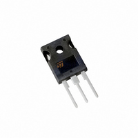
STPS40L15CW STMicroelectronics, STPS40L15CW Datasheet - Page 2

STPS40L15CW
Manufacturer Part Number
STPS40L15CW
Description
DIODE SCHOTTKY 15V 2X20A TO-247
Manufacturer
STMicroelectronics
Specifications of STPS40L15CW
Voltage - Forward (vf) (max) @ If
410mV @ 19A
Current - Reverse Leakage @ Vr
6mA @ 15V
Current - Average Rectified (io) (per Diode)
20A
Voltage - Dc Reverse (vr) (max)
15V
Diode Type
Schottky
Speed
Fast Recovery =< 500ns, > 200mA (Io)
Diode Configuration
1 Pair Common Cathode
Mounting Type
Through Hole, Radial
Package / Case
TO-247-3
Configuration
Common Cathode
Current, Forward
40 A
Current, Reverse
2 A
Current, Surge
310 A
Package Type
TO-247
Primary Type
Rectifier
Resistance, Thermal, Junction To Case
0.85 °C/W
Temperature, Junction, Maximum
+125 °C
Voltage, Forward
0.52 V
Voltage, Reverse
15 V
Lead Free Status / RoHS Status
Lead free / RoHS Compliant
Reverse Recovery Time (trr)
-
Lead Free Status / Rohs Status
RoHS Compliant part
Electrostatic Device
Other names
497-2687-5
Available stocks
Company
Part Number
Manufacturer
Quantity
Price
Company:
Part Number:
STPS40L15CW
Manufacturer:
NXP
Quantity:
5 000
Company:
Part Number:
STPS40L15CW
Manufacturer:
ST
Quantity:
33
Part Number:
STPS40L15CW
Manufacturer:
ST
Quantity:
20 000
STATIC ELECTRICAL CHARACTERISTICS (Per diode)
Pulse test : * tp = 380 s, < 2%
To evaluate the conduction losses use the following equation :
P = 0.18 x I
STPS40L15CW/CT
THERMAL RESISTANCES
Fig. 1: Average forward power dissipation versus
average forward current (per diode).
8
7
6
5
4
3
2
1
0
Fig. 3: Normalized avalanche power derating
versus pulse duration.
0.001
2/5
0.01
Symbol
Symbol
0
R
0.1
PF(av)(W)
R
0.01
1
th
V
I
th (c)
P
R
(j-c)
F
P
ARM
2
ARM p
*
*
(1µs)
(t )
= 0.05
4
F(AV)
0.1
Junction to case
Reverse leakage
current
Forward voltage drop
6
+ 0.008 I
Parameter
8
= 0.1
1
10
IF(av) (A)
t (µs)
p
F
2
12
(RMS)
= 0.2
10
14
16
Tj = 25°C
Tj = 100°C
Tj = 25 C
Tj = 25 C
Tj = 125°C
Tj = 125°C
Parameter
= 0.5
100
=tp/T
18
T
Tests Conditions
20
= 1
tp
1000
22
V
I
I
I
I
Fig. 2: Average forward current versus ambient
temperature ( =1, per diode).
Fig. 4: Normalized avalanche power derating
versus junction temperature.
22
20
18
16
14
12
10
1.2
0.8
0.6
0.4
0.2
F
F
F
F
8
6
4
2
0
R
1
0
= 19 A
= 40 A
= 19 A
= 40 A
0
0
P
IF(av)(A)
= V
P
ARM
ARM p
RRM
=tp/T
(25°C)
(t )
Per diode
25
Coupling
25
T
Total
tp
50
50
Min.
Rth(j-a)=15°C/W
Tamb(°C)
T (°C)
j
75
75
Typ.
0.28
0.42
200
Value
0.85
1.6
0.1
Rth(j-a)=Rth(j-c)
100
100
Max.
0.41
0.52
0.33
0.50
500
6
125
125
°C/W
Unit
Unit
C/W
mA
V
150
150


