BYV32E-150,127 NXP Semiconductors, BYV32E-150,127 Datasheet
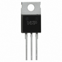
DIODE RECT 150V 20A SOT78

BYV32E-150,127

Manufacturer Part Number
BYV32E-150,127
Description
DIODE RECT 150V 20A SOT78
Manufacturer
NXP Semiconductors
Datasheets

Specifications of BYV32E-150,127

Package / Case
TO-220AB-3
Voltage - Forward (vf) (max) @ If
1.15V @ 20A
Current - Reverse Leakage @ Vr
30µA @ 150V
Current - Average Rectified (io) (per Diode)
20A
Voltage - Dc Reverse (vr) (max)
150V
Reverse Recovery Time (trr)
25ns
Diode Type
Standard
Speed
Fast Recovery =< 500ns, > 200mA (Io)
Diode Configuration
1 Pair Common Cathode
Mounting Type
Through Hole
Product
Ultra Fast Recovery Rectifier
Configuration
Dual Common Cathode
Reverse Voltage
150 V
Forward Voltage Drop
1.15 V
Recovery Time
25 ns
Forward Continuous Current
20 A
Max Surge Current
137 A
Reverse Current Ir
30 uA
Mounting Style
Through Hole
Maximum Operating Temperature
+ 150 C
Minimum Operating Temperature
- 40 C
Lead Free Status / RoHS Status
Lead free / RoHS Compliant
Lead Free Status / RoHS Status
Lead free / RoHS Compliant, Lead free / RoHS Compliant
Other names
934011680127
BYV32E-150
BYV32E-150

Available stocks

Company
Part Number
Manufacturer
Quantity
Price
Part Number:
BYV32E-150,127
Manufacturer:
NXP
Quantity:
15
Philips Semiconductors
FEATURES
• Low forward volt drop
• Fast switching
• Soft recovery characteristic
• Reverse surge capability
• High thermal cycling performance
• Low thermal resistance
GENERAL DESCRIPTION
Dual, ultra-fast, epitaxial rectifier diodes intended for use as output rectifiers in high frequency switched mode power
supplies.
The BYV32E series is supplied in the SOT78 conventional leaded package.
The BYV32EB series is supplied in the SOT404 surface mounting package.
PINNING
LIMITING VALUES
Limiting values in accordance with the Absolute Maximum System (IEC 134).
1 It is not possible to make connection to pin 2 of the SOT404 package
August 2001
Rectifier diodes
ultrafast, rugged
SYMBOL PARAMETER
V
V
V
I
I
I
I
I
T
T
O(AV)
FRM
FSM
RRM
RSM
stg
j
RRM
RWM
R
PIN
tab
1
2
3
anode 1 (a)
cathode (k)
anode 2 (a)
cathode (k)
Peaqk repetitive reverse
voltage
Crest working reverse voltage
Continuous reverse voltage
Average rectified output current square wave; δ = 0.5;
(both diodes conducting)
Repetitive peak forward current t = 25 µs; δ = 0.5;
per diode
Non-repetitive peak forward
current per diode
Repetitive peak reverse current t
per diode
Non-repetitive peak reverse
current per diode
Storage temperature
Operating junction temperature
DESCRIPTION
1
SYMBOL
SOT78 (TO220AB)
a1
CONDITIONS
T
T
t = 10 ms
t = 8.3 ms
sinusoidal; with reapplied
V
t
1
p
p
mb
mb
RWM(max)
= 2 µs; δ = 0.001
= 100 µs
≤ 115 ˚C
≤ 115 ˚C
BYV32E / BYV32EB
tab
k
1
2
1 2 3
a2
3
BYV32E, BYV32EB series
MIN.
-40
QUICK REFERENCE DATA
-
-
-
-
-
-
-
-
-
-
SOT404
-100
100
100
100
V
R
= 100/ 150 V/ 200 V
I
I
V
O(AV)
RRM
t
MAX.
F
Product specification
rr
-150
150
150
150
125
137
150
150
0.2
0.2
20
20
≤ 0.85 V
≤ 25 ns
1
= 0.2 A
= 20 A
tab
2
3
-200
200
200
200
Rev 1.300
UNIT
˚C
˚C
V
V
V
A
A
A
A
A
A

Related parts for BYV32E-150,127

BYV32E-150,127 Summary of contents

Page 1

... Low thermal resistance GENERAL DESCRIPTION Dual, ultra-fast, epitaxial rectifier diodes intended for use as output rectifiers in high frequency switched mode power supplies. The BYV32E series is supplied in the SOT78 conventional leaded package. The BYV32EB series is supplied in the SOT404 surface mounting package. PINNING PIN ...

Page 2

... 100 ˚C R RWM RWM ≥ - / A/µ ≥ -dI /dt = 100 A/µ 0 0. rec / A/µ Product specification BYV32E, BYV32EB series MIN. MAX. UNIT - 8 kV MIN. TYP. MAX. UNIT - - 2.4 K 1 K/W MIN. TYP. MAX. UNIT - 0.72 0. 1.00 1. 0.2 0.6 mA µ ...

Page 3

... Fig.5. Maximum forward dissipation P fr diode; square current waveform where 0 0.0183 Ohms 8 D.U. ’scope 0 0 Fig.6. Maximum forward dissipation P rr2 diode; sinusoidal current waveform where a = form 3 Product specification BYV32E, BYV32EB series I = 0.25A rec trr2 Fig.4. Definition of t rr2 Tmb(max BYV32 D = 1.0 0.5 0.2 0 ...

Page 4

... F F August 2001 100 10 1.0 1.0 100 Fig.10. Maximum IF=1A 0.1 0.01 0.001 1us 100 Fig.11. Transient thermal impedance; per diode; max 1 Product specification BYV32E, BYV32EB series IF=10A -dIF/dt (A/us ˚C; per diode s j Transient thermal impedance, Zth j-mb (K/ 10us 100us ...

Page 5

... Epoxy meets UL94 V0 at 1/8". August 2001 10,3 max 3,7 2,8 3,0 13,5 min 1 0,9 max (3x) 2,54 2,54 Fig.12. SOT78 (TO220AB); pin 2 connected to mounting base. 5 Product specification BYV32E, BYV32EB series 4,5 max 1,3 5,9 min 15,8 max 0,6 2,4 Rev 1.300 ...

Page 6

... August 2001 10.3 max 11 max 15.4 0.85 max (x2) Fig.13. SOT404 : centre pin connected to mounting base. 11.5 9.0 2.0 3.8 5.08 Fig.14. SOT404 : soldering pattern for surface mounting. 6 Product specification BYV32E, BYV32EB series 4.5 max 1.4 max 2.5 0.5 17.5 Rev 1.300 ...

Page 7

... Philips customers using or selling these products for use in such applications their own risk and agree to fully indemnify Philips for any damages resulting from such improper use or sale. August 2001 BYV32E, BYV32EB series 7 Product specification Rev 1.300 ...

Related keywords