PD55015 STMicroelectronics, PD55015 Datasheet - Page 2
PD55015
Manufacturer Part Number
PD55015
Description
RF MOSFET Power N-Ch 40 Volt 5 Amp
Manufacturer
STMicroelectronics
Datasheet
1.PD55015.pdf
(18 pages)
Specifications of PD55015
Minimum Operating Temperature
- 65 C
Mounting Style
SMD/SMT
Product Type
RF MOSFET Power
Transistor Polarity
N-Channel
Configuration
Single
Drain-source Breakdown Voltage
40 V
Gate-source Breakdown Voltage
+/- 20 V
Continuous Drain Current
5 A
Power Dissipation
73 W
Maximum Operating Temperature
+ 165 C
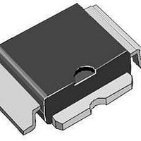
Package / Case
PowerSO-10-4
Channel Type
N
Channel Mode
Enhancement
Drain Source Voltage (max)
40V
Output Power (max)
15W(Min)
Power Gain (typ)@vds
14dB
Frequency (max)
1GHz
Package Type
PowerSO-10RF (Formed lead)
Pin Count
4
Forward Transconductance (typ)
2.5S
Input Capacitance (typ)@vds
89@12.5VpF
Output Capacitance (typ)@vds
60@12.5VpF
Reverse Capacitance (typ)
6.5@12.5VpF
Operating Temp Range
-65C to 165C
Drain Efficiency (typ)
55%
Mounting
Surface Mount
Number Of Elements
1
Power Dissipation (max)
73000mW
Vswr (max)
20(Min)
Screening Level
Military
Lead Free Status / RoHS Status
Lead free / RoHS Compliant
Available stocks
Company
Part Number
Manufacturer
Quantity
Price
Company:

Part Number:
PD55015
Manufacturer:
NICHIA
Quantity:
6 495
Company:
Part Number:
PD55015-E
Manufacturer:
STM
Quantity:
256
Part Number:
PD55015-E
Manufacturer:
ST
Quantity:
20 000
Company:
Part Number:
PD55015S
Manufacturer:
NEC
Quantity:
2 391
Company:
Part Number:
PD55015S-E
Manufacturer:
MICROCHIP
Quantity:
3 000
Part Number:
PD55015S-E
Manufacturer:
ST
Quantity:
20 000
Company:
Part Number:
PD55015STR-E
Manufacturer:
PULSE
Quantity:
694
Part Number:
PD55015STR-E
Manufacturer:
ST
Quantity:
20 000
Part Number:
PD55015TR-E
Manufacturer:
ST
Quantity:
20 000


PD55015 - PD55015S
ELECTRICAL SPECIFICATION (T
STATIC
DYNAMIC
PD55015
2/18
mismatch
FREQ. MHz
Symbol
Symbol
V
SC15200
V
C
C
Load
DS(ON)
P
I
C
I
GS(Q)
g
G
DSS
GSS
OSS
RSS
1dB
GATE
FS
ISS
480
500
520
D
P
V
V
V
V
ALL PHASE ANGLES
V
V
V
V
V
V
V
V
PIN CONNECTION
DD
DD
DD
DD
GS
GS
DS
GS
DS
GS
GS
GS
= 12.5 V I
= 12.5 V I
= 12.5 V I
= 15.5 V I
1.58 + j 0.56
1.53 + j 0.77
1.70 + j 1.17
= 10 V
= 10 V
= 0 V
= 20 V
= 10 V
= 0 V
= 0 V
= 0 V
Z
IN
( )
DQ
DQ
DQ
DQ
= 150 mA
= 150 mA
= 150 mA
= 150 mA
SOURCE
V
V
V
V
V
I
I
I
DS
DS
1.27 - j 1.36
1.51 - j 1.81
1.44 - j 2.13
D
D
D
DS
DS
DS
Test Conditions
DRAIN
CASE
Test Conditions
= 2.5 A
= 2.5 A
= 150 mA
Z
= 28 V
= 0 V
= 12.5 V
= 12.5 V
= 12.5 V
DL
( )
= 25
P
P
P
IMPEDANCE DATA
OUT
OUT
OUT
°
C)
= 15 W f = 500 MHz
= 15 W f = 500 MHz
= 15 W f = 500 MHz
f = 1 MHz
f = 1 MHz
f = 1 MHz
f = 500 MHz
PD55015S
FREQ. MHz
SC13140
480
500
520
876
900
915
Typical Input
Impedance
G
Zin
Min.
20:1
Min.
2.0
2.0
15
12
50
0.33 + j 0.44
0.33 + j 0.70
0.33 + j 0.87
1.30 - j 0.54
1.26 - j 0.30
1.34 - j 0.11
Z
IN
( )
Typ.
Typ.
2.5
6.5
14
55
89
60
D
S
Typical Drain
Load Impedance
Max.
Z
Max.
5.0
0.8
DL
1.18 + j 0.04
1.32 - j 0.22
1.46 - j 0.22
1.36 - j 0.21
1.29 - j 1.03
1.27 - j 0.37
1
1
Z
DL
( )
VSWR
Unit
Unit
mho
dB
W
%
pF
pF
pF
V
V
A
A
Related parts for PD55015
Image
Part Number
Description
Manufacturer
Datasheet
Request
R

Part Number:
Description:
STMicroelectronics [RIPPLE-CARRY BINARY COUNTER/DIVIDERS]
Manufacturer:
STMicroelectronics
Datasheet:
Part Number:
Description:
STMicroelectronics [LIQUID-CRYSTAL DISPLAY DRIVERS]
Manufacturer:
STMicroelectronics
Datasheet:

Part Number:
Description:
BOARD EVAL FOR MEMS SENSORS
Manufacturer:
STMicroelectronics
Datasheet:
Part Number:
Description:
NPN TRANSISTOR POWER MODULE
Manufacturer:
STMicroelectronics
Datasheet:
Part Number:
Description:
TURBOSWITCH ULTRA-FAST HIGH VOLTAGE DIODE
Manufacturer:
STMicroelectronics
Datasheet:
Part Number:
Description:
Manufacturer:
STMicroelectronics
Datasheet:
Part Number:
Description:
DIODE / SCR MODULE
Manufacturer:
STMicroelectronics
Datasheet:
Part Number:
Description:
DIODE / SCR MODULE
Manufacturer:
STMicroelectronics
Datasheet:
Part Number:
Description:
Search -----> STE16N100
Manufacturer:
STMicroelectronics
Datasheet:
Part Number:
Description:
Search ---> STE53NA50
Manufacturer:
STMicroelectronics
Datasheet:
Part Number:
Description:
NPN Transistor Power Module
Manufacturer:
STMicroelectronics
Datasheet:
Part Number:
Description:
DIODE / SCR MODULE
Manufacturer:
STMicroelectronics
Datasheet: