FLUKE-177 ESFP Fluke Electronics, FLUKE-177 ESFP Datasheet
FLUKE-177 ESFP
Specifications of FLUKE-177 ESFP
177 ESFP
614-1020


FLUKE-177 ESFP Summary of contents
Page 1
... May 2003 (English) © 2003 Fluke Corporation. All rights reserved. Printed in USA. Models 175, 177, 179 True RMS Multimeters ® Users Manual ...
Page 2
... Each Fluke 20, 70, 80, 170 and 180 Series DMM will be free from defects in material and workmanship for its lifetime. As used herein, “life- time” is defined as seven years after Fluke discontinues manufacturing the product, but the warranty period shall be at least ten years from the date of purchase. This warranty does not cover fuses, disposable batteries, damage from neglect, misuse, contamination, alteration, accident or abnormal conditions of operation or handling, including failures caused by use outside of the product’ ...
Page 3
... Contacting Fluke ................................................................................................................... 1 "Warning" and "Caution" Statements..................................................................................... 1 Unsafe Voltage...................................................................................................................... 1 Test Lead Alert ...................................................................................................................... 1 Battery Saver ("Sleep Mode")................................................................................................ 2 Terminals .............................................................................................................................. 2 Rotary Switch Positions......................................................................................................... 2 Display .................................................................................................................................. 3 MIN MAX AVG Recording Mode ........................................................................................... 4 Display HOLD and AutoHOLD Modes ................................................................................... 4 YELLOW Button .................................................................................................................... 4 Display Backlight (Model 177 and 179 Only) ......................................................................... 4 Manual Ranging and Autoranging ......................................................................................... 5 Power-Up Options ...
Page 4
To avoid possible electrical shock or personal injury, follow these guidelines: Use the Meter only as specified in this manual or the protection provided by the Meter might be impaired. Do not use the Meter or test leads if they ...
Page 5
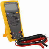
... The Fluke Model 175, Model 177, and Model 179 are battery- powered, true-RMS multimeters (hereafter "the Meter") with a 6000-count, 3 3/4-digit display and a bar graph. This manual applies to all three models. All figures show the Model 179. These meters meet CAT III and CAT IV IEC 61010 standards. ...
Page 6
Models 175, 177 & 179 Users Manual Battery Saver ("Sleep Mode") The Meter enters the "Sleep mode" and blanks the display if there is no function change or button press for 20 minutes. To disable the Sleep mode, hold down ...
Page 7
Display . No. Symbol s 1 Continuity test Diode test Negative readings Unsafe voltage. Voltage voltage overload (OL Display HOLD is enabled. ...
Page 8
Models 175, 177 & 179 Users Manual MIN MAX AVG Recording Mode The MIN MAX AVG recording mode captures the minimum and maximum input values, and calculates a running average of all readings. When a new high or low is ...
Page 9
Manual Ranging and Autoranging The Meter has both Manual range and Autorange modes. In the Autorange mode, the Meter selects the range with the best resolution. In the Manual Range mode, you override Autorange and select the range yourself. When ...
Page 10
Models 175, 177 & 179 Users Manual Making Basic Measurements The figures on the following pages show how to make basic measurements. When connecting the test leads to the circuit or device, connect the common (COM) test lead before connecting ...
Page 11
Testing for Continuity HOLD MIN MAX RANGE Measuring Temperature (Model 179 Only) HOLD MIN MAX RANGE RANGE 80BK1 Type K Thermocouple Probe X W Warning: Do not connect 80BK1 to live circuits. Testing Diodes Good Diode HOLD MIN MAX RANGE ...
Page 12
Models 175, 177 & 179 Users Manual Measuring Current X W Warning To avoid personal injury or damage to the Meter: Never attempt to make an in-circuit current measure- ment when the open-circuit potential to earth is ...
Page 13
Measuring Frequency X W Warning To avoid electrical shock, disregard the bar graph for frequencies > 1 kHz. If the frequency of the measured signal is > 1 kHz, the bar graph is unspecified. The Meter measures the frequency of ...
Page 14
... Use ONLY fuses with the amperage, interrupt, voltage, and speed ratings specified. Replace the battery as soon as the low battery indicator ( <. AIK12F.EPS F1 Fuse, 440 mA, 1000 V, FAST F2 Fuse 1000 V, FAST B1 Battery Alkaline, NEDA 1604 / 1604A XW Warning b ) appears AIK13F.EPS Fluke PN 943121 Fluke PN 803293 Fluke PN 614487 b ...
Page 15
Specifications Accuracy is specified for 1 yr after calibration, at operating temperatures with relative humidity Accuracy specifications take the form of: Maximum voltage between any terminal and earth ...
Page 16
Models 175, 177 & 179 Users Manual 1 Function Range AC Volts 2,3 600.0 mV 6.000 V 60.00 V 600.0 V 1000 600 Volts 6.000 V 60.00 V 600.0 V 1000 V Continuity 600 Ohms ...
Page 17
Function Range 4 DC Amps 60.00 mA 400.0 mA 6.000 A 10. 99.99 Hz (AC- or DC- coupled, 999 input ) 9.999 kHz 99.99 kHz Temperature - +400 C -40 ...
Page 18
Models 175, 177 & 179 Users Manual Function Overload Protection Volts AC 1000 V RMS Volts DC 1000 V RMS 2 mV/ T 1000 V RMS 2 Ohms 1000 V RMS 2 Continuity/Diode 1000 V RMS test ...