4010A B&K Precision, 4010A Datasheet - Page 10
4010A
Manufacturer Part Number
4010A
Description
FUNCTION GENERATOR 2MHZ
Manufacturer
B&K Precision
Type
Functionr
Specifications of 4010A
Includes
Cable
Frequency Band
0.2Hz ~ 2MHz (7 Ranges)
Display Type
No Display
Supply Voltage
120V/230V
Signal Types
Sine, Square, Triangle, Ramp, Pulse
Frequency
0.2 Hz to 2 MHz
Equipment Type
Function Generators
Bandwidth
2MHz
Modulation Type
FM
External Height
114mm
External Width
298mm
External Depth
264mm
Leaded Process Compatible
No
Peak Reflow Compatible (260 C)
No
Rohs Compliant
No
Signal Generator Type
Function
Number Of Channels
-
Lead Free Status / Rohs Status
Lead free / RoHS Compliant
Other names
BK4010A


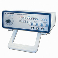
versatile instrument, capable of producing a variety of output
waveforms over a broad range of frequencies. To gain a working
familiarity with the unit, it is recommended that it be connected
initially to an oscilloscope, so that the effects of the various
controls on the output waveforms can be observed. Use this
manual as required for reference until becoming accustomed to
the operating procedures.
FREQUENCY AND WAVEFORM SELECTION
l. Initially, verify that the DUTY CYCLE (14), CMOS
2. Plug the unit into an appropriate power source and turn it on
3. Select the desired waveform (SINE, SQUARE, or
4. Select the frequency of the waveform by engaging one of
5. Rotate the FREQUENCY control (15) to set the output
The B+K Precision Model 4010A Function Generator is a
LEVEL (13), DC OFFSET (12), -20dB (11) switches are
in the OUT position (released). This will produce a
symmetrical waveform unaffected by the other controls.
by engaging the POWER switch (1).
TRIANGLE) by engaging one of the FUNCTION switches
(3). Phase relationships of the waveforms are shown in Fig.
2.
the RANGE switches (2).
frequency to the desired value. The frequency selected is
available at the OUTPUT jack (6). In addition, a digital
signal, either TTL or CMOS is available at the TTL/CMOS
jack (7) (refer to the “TTL/CMOS OUTPUT” section of this
manual).
OPERATING INSTRUCTIONS
10
6. Adjust the amplitude of the output as desired using the
OUTPUT LEVEL control (4). Rotation of this control
varies the amplitude from maximum to 20 dB below
maximum. An additional attenuation of -20 dB is
available by pushing in the -20dB switch (11). The
attenuation factors can be combined for a total of -40
dB. The maximum signal level is 10 V p-p (into 50 Ω).
Figure 2. Output Waveform and Phase
Relationship