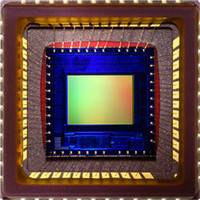
MT9V131C12STC Aptina LLC, MT9V131C12STC Datasheet - Page 8

MT9V131C12STC
Manufacturer Part Number
MT9V131C12STC
Description
SENSOR IMAGE VGA COLOR 48CLCC
Manufacturer
Aptina LLC
Series
Micron®DigitalClarity®r
Type
CMOS Imagingr
Datasheet
1.MT9V131C12STC.pdf
(14 pages)
Specifications of MT9V131C12STC
Package / Case
48-CLCC
Pixel Size
5.6µm x 5.6µm
Active Pixel Array
640H x 480V
Frames Per Second
15 ~ 90
Voltage - Supply
2.8V
Supply Voltage Range
2.55V To 3.05V
Operating Temperature Range
-20°C To +60°C
Digital Ic Case Style
CLCC
No. Of Pins
48
Supply Voltage Max
3.05V
Supply Voltage
RoHS Compliant
Ic Function
Digital Image Sensor
Rohs Compliant
Yes
Lead Free Status / RoHS Status
Lead free / RoHS Compliant
For Use With
557-1243 - KIT HEADBOARD FOR MT9V131557-1242 - KIT DEMO FOR MT9V131
Lead Free Status / RoHS Status
Lead free / RoHS Compliant
Other names
557-1241
Figure 6:
PDF: 09005aef824c99b3/Source: 009005aef824c99bb
MT9V131_LDS_2.fm - Rev. B 3/07 EN
Image Flow Processor Block Diagram
The MT9V131 features smooth, continuous zoom and pan. This functionality is avail-
able when the IFP output is downsized in the decimation block. The decimation block
can downsize the original VGA image to any integer size, including QVGA, QQVGA, CIF,
and QCIF with no loss to the field of view. The user can program the desired size of the
output image in terms of horizontal and vertical pixel count. In addition, the user can
program the size of a region for downsizing. Continuous zoom is achieved every time
the region of interest is less than the entire VGA image. The maximum zoom factor is
equal to the ratio of VGA to the size of the region of interest. For example, an image
rendered on a 160 x 120 display can be zoomed by 640/160 = 480/120 = 4 times. Contin-
uous pan is achieved by adjusting the starting coordinates of the region of interest.
Also, a fixed 2X up-zoom is implemented by means of windowing down the sensor core.
In this mode, the IFP receives a QVGA-sized input data and outputs a VGA-size image.
The sub-window can be panned both vertically and horizontally by programming
sensor core registers.
The MT9V131 supports both LED and Xenon-type flash light sources using a dedicated
output pad. For Xenon devices, the pad generates a strobe to fire when the imager's
shutter is fully open. For LED, the pad can be asserted or de-asserted asynchronously.
Flash modes are configured and engaged over the two-wire serial interface using IFP .
GAMMA CORRECTION
OUTPUT FORMATTING
COLOR CORRECTION
LENS CORRECTION
IMAGE SENSOR
DEMOSAICING
MT9V131: 1/4-Inch SOC VGA CMOS Digital Image Sensor
FLICKER AVOIDANCE
8
FLASH CONTROL
AE, AWB,
Micron Technology, Inc., reserves the right to change products or specifications without notice.
Image Flow Processor
©2006 Micron Technology, Inc. All rights reserved.
Preliminary


