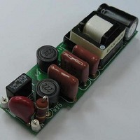
RDK-251 Power Integrations, RDK-251 Datasheet - Page 10

RDK-251
Manufacturer Part Number
RDK-251
Description
KIT REF DESIGN FOR LNK457D
Manufacturer
Power Integrations
Series
LinkSwitch®-PLr
Datasheet
1.RDK-251.pdf
(60 pages)
Specifications of RDK-251
Current - Output / Channel
350mA
Outputs And Type
1, Isolated
Voltage - Output
12 ~ 18 V
Features
Dimmable
Voltage - Input
90 ~ 265VAC
Utilized Ic / Part
LNK457D
Output Voltage
12 V
Input / Supply Voltage (max)
265 VAC
Input / Supply Voltage (min)
90 VAC
Duty Cycle (max)
39.9 %
Mounting Style
Through Hole
Output Current
350 mA
Output Power
5 W
Lead Free Status / RoHS Status
Lead free / RoHS Compliant
Other names
596-1345
Available stocks
Company
Part Number
Manufacturer
Quantity
Price
Company:
Part Number:
RDK-251
Manufacturer:
Power Integrations
Quantity:
135
For non-dimming application these components can simply be omitted and jumpers used
to replace R7 and R8 giving higher efficiency with no change in other performance
characteristics.
4.2 Input EMI Filtering and Input Rectification
The EMI filter was optimized to minimize the impact on dimming performance. Resistor
R20 is a fusible resistor. Fusible types are selected to fail open-circuit should a
component failure cause excessive input current. Film types (vs. wirewound) are
acceptable compared to a non or passive PFC solution. This reduces the instantaneous
dissipation as the input capacitance charges, however, a 2 w rating is recommended for
designed that operate at high line. In addition they limit the inrush current caused when a
phase leading TRIAC dimmer turns on and capacitors C4 and C5 charge. The worst case
condition (maximum inrush current) occurs when the TRIAC turns on at 90 or 270
degrees, which correspond to the peaks of the AC waveform. Finally they act to damp
any current ringing between the AC line impedance and the input stage of the supply
again caused by the inrush current when leading edge TRIAC dimmers turn on.
Two differential pi (π) filter EMI stages are used with C1, R2, L1 and C2 forming one
stage and C4, L2, R9 and C5 the second. It was found during testing that C1 was not
required to meet conducted EMI limits and was therefore not populated.
The incoming AC is rectified by BR1 and filtered by C4 and C5. The total effective input
capacitance, the sum of C4, C5 and C6, was selected to assure correct zero crossing
detection of the AC input by the LinkSwitch-PL device, necessary correct operation and
best performance during dimming.
4.3 Active Damper
The active damper network is used to limit the inrush current, associated voltage spikes
and ringing when the TRIAC within a dimmer turns on. This connects a resistance (R7
and R8) in series with the input rectifier for a short period of each AC half-cycle, it is then
bypassed for the remainder of the AC cycle by a parallel SCR (Q3). Resistor R3, R4 and
C3 determines the delay before the turn-on of Q3.
4.4 Bleeder
Resistor R10, R11 and C6 form a bleeder network which ensures the initial input current
is high enough meet the TRIAC holding current requirement, especially during small
TRIAC conduction angles.
For non-dimming application, both the active damper and bleeder network may be
removed. To achieve this, the following parts can be deleted
C6 and C3. Replace 0 for the following locations: R7, R8, and R20.
Power Integrations, Inc.
Tel: +1 408 414 9200 Fax: +1 408 414 9201
www.powerint.com
:
Q3, R20, R3, R4, R10, R11,
Page 10 of 60


