SP7600EB Exar Corporation, SP7600EB Datasheet - Page 2
SP7600EB
Manufacturer Part Number
SP7600EB
Description
EVAL BOARD FOR SP7600
Manufacturer
Exar Corporation
Specifications of SP7600EB
Current - Output / Channel
2A
Outputs And Type
1, Non-Isolated
Features
PWM Brightness control
Voltage - Input
4.5 ~ 29 V
Utilized Ic / Part
SP7600
Maximum Operating Temperature
+ 85 C
Minimum Operating Temperature
- 40 C
Product
Display Modules
Core Chip
SP7600
No. Of Outputs
1
Output Current
2A
Output Voltage
200mV
Dimming Control Type
PWM
Development Tool Type
Hardware - Eval/Demo Board
Mcu Supported Families
SP7600
Lead Free Status / RoHS Status
Contains lead / RoHS non-compliant
Voltage - Output
-
Lead Free Status / Rohs Status
Lead free / RoHS Compliant
Other names
1016-1233


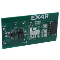
_______________________________________________ USING THE EVALUATION BOARD
1) Powering Up the SP7600 Circuit
The SP7600 Evaluation Board can be powered from a 4.5V to 29V power supply. Connect the power
supply with short leads directly to the “Vin” and “GND” posts.
2) Setting the output current
Externally connected LEDs need to be connected anode to the VOUT pin and cathode to the Vfb pin. As
many as 6 series connected LEDs may be used, depending on the input voltage range available. The
maximum output current is 3A but the user should take care not to exceed the maximum junction
temperature, 125°C. Up to 2A maximum is possible in almost all conditions. The board also has SMT
pads available for LEDs to be mounted in the LED1 position for a Luxeon K2 LED, and LED2, LED3 and
LED4 positions for Luxeon Rebel LEDs. The total output current of the SP7600 is controlled by the VFB
pin voltage setpoint of 200mV. Use a resistor at RA to set the output current by the formula:
Iout = Vfb/RA
where RA is the parallel combination of Ra and any of the resistors Rb, Rc or Rd.
If Ra, Rb, Rc and Rd are used then RA = 1/(1/Ra + 1/Rb + 1/Rc + 1/Rd)
Standard SP7600EB Evaluation Board Example:
Iout = Vfb/RA = 200mV/0.22ohm = 1A
3) Dimming
The SP7600 can be pulse width modulated using a signal applied to the DIM post. The DIM signal
connects to the VFB pin through a 1N4148 diode and will shutdown the SP7600 when DIM = H and turn-
on the SP7600 when DIM = L. The DIM signal needs to be greater than 600mV minimum to turn-off the
SP7600 and less than 200mV to fully turn-on the SP7600. It is recommended to use a signal with DIM =
1V or more for OFF and 0V for ON. The user should note that the logic is reversed relative to many
other PWM controlled LED drivers. In other words a logic level high at 20% duty cycle will result in
approximately an 80% duty cycle for the LED. Recommended modulation frequencies are from 100Hz to
200Hz with 10 – 90% duty cycle, 500Hz with 10 – 80% duty cycle, and 1000Hz with 10 – 70% duty cycle.
Figures 2 & 3 show the output response at the maximum PWM DIM signal of 1000Hz. See figure 4 for
100Hz to 1000Hz duty cycle response for two Luxeon K2 LEDs in parallel at 2A total current.
12/17/07
SP7600 Evaluation Board Manual
© 2007 Exar Corporation
Page 2 of 5
Related parts for SP7600EB
Image
Part Number
Description
Manufacturer
Datasheet
Request
R

Part Number:
Description:
2amp, 29v Buck Converter For Led Driver Applications
Manufacturer:
Exar Corporation
Datasheet:
Part Number:
Description:
BiCMOS Fixed, Quad, Voltage Output, Single or Dual Supply 8-Bit Digital-to-Analog Converter
Manufacturer:
Exar Corporation
Datasheet:
Part Number:
Description:
Manufacturer:
Exar Corporation
Datasheet:
Part Number:
Description:
Voltage-Controlled Oscillator
Manufacturer:
Exar Corporation
Datasheet:
Part Number:
Description:
INTEGRATED LINE TRANSMITTER
Manufacturer:
Exar Corporation
Datasheet:
Part Number:
Description:
Monolithic Function Generator
Manufacturer:
Exar Corporation
Datasheet:
Part Number:
Description:
CMOS Microprocessor Compatible Double-Buffered 12-Bit Digital-to-Analog Converter
Manufacturer:
Exar Corporation
Datasheet:
Part Number:
Description:
CMOS 6 BIT HIGH SPEED ANALOG TO DIGITAL CONVERTER
Manufacturer:
Exar Corporation
Datasheet:
Part Number:
Description:
Manufacturer:
Exar Corporation
Datasheet:
Part Number:
Description:
Manufacturer:
Exar Corporation
Datasheet:
Part Number:
Description:
8-Channel, Voltage Output 10 MHz Input Bandwidth 8-Bit Multiplying DACs with Serial Digital Data Por
Manufacturer:
Exar Corporation
Datasheet:
Part Number:
Description:
15 V CMOS Multiplying10-Bit Digital-to-Analog Converter
Manufacturer:
Exar Corporation
Datasheet:
Part Number:
Description:
Monolithic Function Generator
Manufacturer:
Exar Corporation
Datasheet: