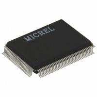
KSZ8893MQL AM Micrel Inc, KSZ8893MQL AM Datasheet - Page 30

KSZ8893MQL AM
Manufacturer Part Number
KSZ8893MQL AM
Description
2+1 Port 10/100 Switch W/Tranceivers & Frame Buffers, 128-Ld PQFP( )
Manufacturer
Micrel Inc
Specifications of KSZ8893MQL AM
Controller Type
Ethernet Switch Controller
Interface
MII, RMII, SNI
Voltage - Supply
3.1 V ~ 3.5 V
Operating Temperature
0°C ~ 70°C
Mounting Type
Surface Mount
Package / Case
128-MQFP, 128-PQFP
Number Of Primary Switch Ports
3
Internal Memory Buffer Size
32
Operating Supply Voltage (typ)
3.3V
Fiber Support
Yes
Integrated Led Drivers
Yes
Power Supply Type
Analog/Digital
Package Type
PQFP
Data Rate (typ)
10/100Mbps
Vlan Support
Yes
Operating Temperature (max)
85C
Operating Temperature (min)
-40C
Pin Count
128
Mounting
Surface Mount
Jtag Support
No
Operating Supply Voltage (max)
3.5V
Operating Supply Voltage (min)
3.1V
Operating Temperature Classification
Industrial
Data Rate
100Mbps
Lead Free Status / RoHS Status
Lead free / RoHS Compliant
For Use With
576-1603 - EVAL KIT EXPERIMENTAL KSZ8893MQL
Current - Supply
-
Lead Free Status / RoHS Status
Compliant, Lead free / RoHS Compliant
Other names
576-3091
10BASE-T Receive
On the receive side, input buffers and level detecting squelch circuits are employed. A differential input receiver
circuit and a phase-locked loop (PLL) perform the decoding function. The Manchester-encoded data stream is
separated into clock signal and NRZ data. A squelch circuit rejects signals with levels less than 400mV or with
short pulse widths to prevent noise at the RXP-or-RXM input from falsely triggering the decoder. When the input
exceeds the squelch limit, the PLL locks onto the incoming signal and the KSZ8893MQL/MBL decodes a data
frame. The receiver clock is maintained active during idle periods in between data reception.
Power Management
The KSZ8893MQL/MBL features a per-port power down mode. To save power, a PHY port that is not in use can
be powered down via port control register, or MIIM PHY register.
In addition, there is a full chip power down mode. When activated, the entire chip is powered down.
MDI/MDI-X Auto Crossover
To eliminate the need for crossover cables between similar devices, the KSZ8893MQL/MBL supports HP Auto
MDI/MDI-X and IEEE 802.3u standard MDI/MDI-X auto crossover. HP Auto MDI/MDI-X is the default.
The auto-sense function detects remote transmit and receive pairs and correctly assigns transmit and receive
pairs for the KSZ8893MQL/MBL device. This feature is extremely useful when end users are unaware of cable
types, and also, saves on an additional uplink configuration connection. The auto-crossover feature can be
disabled through the port control registers, or MIIM PHY registers.
The IEEE 802.3u standard MDI and MDI-X definitions are:
December 2007
RJ-45 Pins
1
2
3
6
MDI
Table 2. MDI/MDI-X Pin Definitions
Signals
RD+
TD+
RD-
TD-
30
RJ-45 Pins
1
2
3
6
MDI-X
Signals
RD+
TD+
RD-
TD-
M9999-121007-1.5


