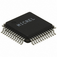
KSZ8851-16MLL Micrel Inc, KSZ8851-16MLL Datasheet - Page 12

KSZ8851-16MLL
Manufacturer Part Number
KSZ8851-16MLL
Description
Single Ethernet Port + Generic (16-bit) Bus Interface( )
Manufacturer
Micrel Inc
Specifications of KSZ8851-16MLL
Controller Type
Ethernet Controller, MAC/PHY
Interface
Bus
Voltage - Supply
1.8V, 2.5V, 3.3V
Operating Temperature
0°C ~ 70°C
Mounting Type
Surface Mount
Package / Case
48-LQFP
Operating Supply Voltage (typ)
3.3V
Operating Temperature Classification
Commercial
Mounting
Surface Mount
Pin Count
48
Lead Free Status / RoHS Status
Lead free / RoHS Compliant
For Use With
576-3292 - BOARD EVALUATION KSZ8851-16MLL
Current - Supply
-
Lead Free Status / RoHS Status
Compliant, Lead free / RoHS Compliant
Other names
576-3252
Available stocks
Company
Part Number
Manufacturer
Quantity
Price
Company:
Part Number:
KSZ8851-16MLL
Manufacturer:
Kendin
Quantity:
1 490
Part Number:
KSZ8851-16MLL
Manufacturer:
MICREL/麦瑞
Quantity:
20 000
Part Number:
KSZ8851-16MLLI
Manufacturer:
MICREL/麦瑞
Quantity:
20 000
Company:
Part Number:
KSZ8851-16MLLI TR
Manufacturer:
Kendin
Quantity:
225
Company:
Part Number:
KSZ8851-16MLLI TR
Manufacturer:
Micrel Inc
Quantity:
10 000
Company:
Part Number:
KSZ8851-16MLLJ
Manufacturer:
Micrel
Quantity:
2 099
Company:
Part Number:
KSZ8851-16MLLTR
Manufacturer:
TIMONTA
Quantity:
23
Company:
Part Number:
KSZ8851-16MLLU
Manufacturer:
Micrel
Quantity:
2 019
August 2009
Micrel, Inc.
Pin Number
12
13
14
15
16
17
18
19
20
21
22
23
24
25
26
27
28
29
30
31
32
33
34
35
36
37
VDD_D1.8
VDD_A1.8
VDD_A3.3
Pin Name
VDD_IO
AGND
AGND
DGND
DGND
DGND
EECS
RXM1
RXP1
TXM1
RSTN
TXP1
SD15
SD14
SD13
SD12
SD11
SD10
ISET
CSN
SD9
X1
X2
I/O (pd)
I/O (pd)
I/O (pd)
I/O (pd)
I/O (pd)
I/O (pd)
I/O (pd)
Type
Gnd
Opd
Gnd
Gnd
Gnd
Gnd
Ipu
I/O
I/O
I/O
I/O
Ipu
P
O
O
P
P
P
I
Pin Function
Chip Select Not
Chip select for the shared data bus access enable, active Low.
Analog ground
1.8V analog power supply from VDD_CO1.8 (pin 8) with appropriate filtering. If VDD_IO is
1.8V, this pin must be supplied power from the same source as pins 27, 38 and 46
(VDD_IO) with appropriate filtering.
EEPROM Chip Select
This signal is used to select an external EEPROM device.
Port 1 physical receive (MDI) or transmit (MDIX) signal (+ differential).
Port 1 physical receive (MDI) or transmit (MDIX) signal (– differential).
Analog ground.
Port 1 physical transmit (MDI) or receive (MDIX) signal (+ differential).
Port 1 physical transmit (MDI) or receive (MDIX) signal (– differential).
3.3V analog VDD input power supply with well decoupling capacitors.
Set physical transmits output current.
Pull-down this pin with a 3.01K 1% resistor to ground.
Reset Not
Hardware reset pin (active Low). This reset input is required minimum of 10ms low after
stable supply voltage 3.3V.
25MHz crystal or oscillator clock connection.
Pins (X1, X2) connect to a crystal. If an oscillator is used, X1 connects to a 3.3V tolerant
oscillator and X2 is a no connect.
Note: Clock requirement is ±50ppm for either crystal or oscillator.
Digital ground
3.3V, 2.5V or 1.8V digital VDD input power supply for IO with well decoupling capacitors.
Digital ground
1.8V digital power supply from VDD_CO1.8 (pin 8) with appropriate filtering. If VDD_IO is
1.8V, this pin must be supplied power from the same source as pins 27, 38 and 46
(VDD_IO) with appropriate filtering.
Shared Data Bus bit 15. Data D15 access when CMD=0. Byte Enable 3 at double-word
boundary access (BE3, 4th byte enable and active high) in 16-bit mode when CMD=1.
This pin must be tied to GND in 8-bit bus mode.
Shared Data Bus bit 14. Data D14 access when CMD=0. Byte Enable 2 at double-word
boundary access (BE2, 3rd byte enable and active high) in 16-bit mode when CMD=1.
This pin must be tied to GND in 8-bit bus mode.
Shared Data Bus bit 13. Data D13 access when CMD=0. Byte Enable 1 at double-word
boundary access (BE1, 2nd byte enable and active high) in 16-bit mode when CMD=1.
This pin must be tied to GND in 8-bit bus mode.
Shared Data Bus bit 12. Data D12 access when CMD=0. Byte Enable 0 at double-word
boundary access (BE0, 1st byte enable and active high) in 16-bit mode when CMD=1.
This pin must be tied to GND in 8-bit bus mode.
Shared Data Bus bit 11. Data D11 access when CMD=0. Don’t care when CMD=1. This
pin must be tied to GND in 8-bit bus mode.
Shared Data Bus bit 10. Data D10 access when CMD=0. Don’t care when CMD=1. This
pin must be tied to GND in 8-bit bus mode.
Shared Data Bus bit 9. Data D9 access when CMD=0. Don’t care when CMD=1. This pin
must be tied to GND in 8-bit bus mode.
Digital ground
12
KSZ8851-16MLL/MLLI
M9999-083109-2.0


