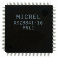
KSZ8841-16MVLI Micrel Inc, KSZ8841-16MVLI Datasheet - Page 18

KSZ8841-16MVLI
Manufacturer Part Number
KSZ8841-16MVLI
Description
Single Ethernet Port + Generic (8, 16-bit) Bus Interface( )
Manufacturer
Micrel Inc
Specifications of KSZ8841-16MVLI
Controller Type
Ethernet Controller, MAC
Interface
Bus
Voltage - Supply
3.1 V ~ 3.5 V
Operating Temperature
-40°C ~ 85°C
Mounting Type
Surface Mount
Package / Case
128-LQFP
Operating Supply Voltage (typ)
3.3V
Operating Temperature Classification
Industrial
Mounting
Surface Mount
Pin Count
128
Lead Free Status / RoHS Status
Lead free / RoHS Compliant
For Use With
576-1632 - BOARD EVALUATION KSZ8841-16MVL
Current - Supply
-
Lead Free Status / RoHS Status
Compliant, Lead free / RoHS Compliant
Other names
576-2114
KSZ8841-16MVLI
KSZ8841-16MVLI
Available stocks
Company
Part Number
Manufacturer
Quantity
Price
Company:
Part Number:
KSZ8841-16MVLI
Manufacturer:
MICREL
Quantity:
441
October 2007
Micrel, Inc.
Ball Number
B7
C7
A6
B6
A5
B5
A4
B4
A3
B3
C3
A2
B2
A1
B1
Ball Name
CYCLEN
VLBUSN
P1LED3
PWRDN
EEDO
EECS
ARDY
EEEN
ADSN
EESK
EEDI
SWR
WRN
RDN
AEN
Type
Opu
Opd
Opd
Opd
Opd
Ipd
Ipd
Ipd
Ipd
Ipd
Ipd
Ipu
Ipd
Ipd
Ipu
Ball Function
Active Low output signal, asserted when AEN is Low and A15-A4 decode to the
KSZ8841M address programmed into the high byte of the base address register.
LDEVN is a combinational decode of the Address and AEN signal.
Read Strobe Not
Asynchronous read strobe, active Low.
EEPROM Chip Select
Asynchronous Ready
ARDY may be used when interfacing asynchronous buses to extend bus access
cycles. It is asynchronous to the host CPU or bus clock. This ball needs an
external 4.7K pull-up resistor.
Cycle Not
For VLBus-like mode cycle signal; this ball follows the addressing cycle to signal
the command cycle.
For burst mode (32-bit interface only), this ball stays High for read cycles and
Low for write cycles.
VLBus-like Mode
Pull-down or float: Bus interface is configured for synchronous mode.
Pull-up: Bus interface is configured for 8-bit or 16-bit asynchronous mode or
EISA-like burst mode.
EEPROM Enable
EEPROM is enabled and connected when this ball is pull-up.
EEPROM is disabled when this ball is pull-down or no connect.
Port 1 LED indicator
See the description in balls A10, B10, and C10.
EEPROM Data Out
This ball is connected to DI input of the serial EEPROM.
EEPROM Serial Clock
A 4
on-chip bus speed @ 125 MHz) serial output clock cycle to load configuration
data from the serial EEPROM.
EEPROM Data In
This ball is connected to DO output of the serial EEPROM when EEEN is pull-
up.
This ball can be pull-down for 8-bit bus mode, pull-up for 16-bit bus mode or
don’t care for 32-bit bus mode when EEEN is pull-down (without EEPROM).
Synchronous Write/Read
Write/Read signal for synchronous bus accesses. Write cycles when high and
Read cycles when low.
Address Enable
Address qualifier for the address decoding, active Low.
Write Strobe Not
Asynchronous write strobe, active Low.
Address Strobe Not
For systems that require address latching, the rising edge of ADSN indicates the
latching moment of A15-A1 and AEN.
Full-chip power-down. Low = Power down; High or floating = Normal operation.
µ
s (OBCR[1:0]=11 on-chip bus speed @ 25 MHz) or 800 ns (OBCR[1:0]=00
18
KSZ8841-16/32 MQL/MVL/MBL
M9999-102207-1.6


