ADXL345BCCZ-RL Analog Devices Inc, ADXL345BCCZ-RL Datasheet - Page 28
ADXL345BCCZ-RL
Manufacturer Part Number
ADXL345BCCZ-RL
Description
Digital Output Three-Axis Accel 4K RL
Manufacturer
Analog Devices Inc
Series
iMEMS®r
Datasheet
1.EVAL-ADXL345Z.pdf
(40 pages)
Specifications of ADXL345BCCZ-RL
Design Resources
Sensing Low-g Acceleration Using ADXL345 Digital Accelerometer Connected to ADuC7024 (CN0133)
Axis
X, Y, Z
Acceleration Range
±2g, 4g, 8g, 16g
Sensitivity
256LSB/g, 128LSB/g, 64LSB/g, 32LSB/g
Voltage - Supply
2 V ~ 3.6 V
Output Type
Digital
Bandwidth
6.25Hz ~ 3.2kHz Selectable
Interface
I²C, SPI
Mounting Type
Surface Mount
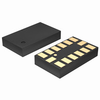
Package / Case
14-LGA
Package Type
LGA
Operating Supply Voltage (typ)
2.5V
Operating Supply Voltage (max)
3.6V
Operating Temperature (min)
-40C
Operating Temperature (max)
85C
Operating Temperature Classification
Industrial
Product Depth (mm)
3mm
Product Length (mm)
5mm
Mounting
Surface Mount
Pin Count
14
Lead Free Status / RoHS Status
Lead free / RoHS Compliant
Lead Free Status / RoHS Status
Lead free / RoHS Compliant
Other names
ADXL345BCCZ-RLTR
Available stocks
Company
Part Number
Manufacturer
Quantity
Price
Company:

Part Number:
ADXL345BCCZ-RL7
Manufacturer:
POWER
Quantity:
14 300


ADXL345
APPLICATIONS INFORMATION
POWER SUPPLY DECOUPLING
A 1 μF tantalum capacitor (C
(C
recommended to adequately decouple the accelerometer from
noise on the power supply. If additional decoupling is necessary,
a resistor or ferrite bead, no larger than 100 Ω, in series with V
may be helpful. Additionally, increasing the bypass capacitance
on V
ceramic capacitor may also improve noise.
Care should be taken to ensure that the connection from the
ADXL345 ground to the power supply ground has low impedance
because noise transmitted through ground has an effect similar
to noise transmitted through V
V
on the V
the supplies, as previously mentioned, may be necessary.
MECHANICAL CONSIDERATIONS FOR MOUNTING
The ADXL345 should be mounted on the PCB in a location
close to a hard mounting point of the PCB to the case. Mounting
the ADXL345 at an unsupported PCB location, as shown in
Figure 44, may result in large, apparent measurement errors
due to undampened PCB vibration. Locating the accelerometer
near a hard mounting point ensures that any PCB vibration at
the accelerometer is above the accelerometer’s mechanical sensor
resonant frequency and, therefore, effectively invisible to the
accelerometer. Multiple mounting points, close to the sensor,
and/or a thicker PCB also help to reduce the effect of system
resonance on the performance of the sensor.
DD I/O
I/O
INTERRUPT
CONTROL
) at V
S
to a 10 μF tantalum capacitor in parallel with a 0.1 μF
be separate supplies to minimize digital clocking noise
S
supply. If this is not possible, additional filtering of
DD I/O
Figure 44. Incorrectly Placed Accelerometers
placed close to the ADXL345 supply pins is
MOUNTING POINTS
C
Figure 43. Application Diagram
ACCELEROMETERS
S
INT1
INT2
V
V
S
PCB
S
SDO/ALT ADDRESS
ADXL345
S
) at V
GND
SDA/SDI/SDIO
S
. It is recommended that V
SCL/SCLK
V
V
S
DD I/O
DD I/O
and a 0.1 μF ceramic capacitor
CS
C
IO
3- OR 4-WIRE
SPI OR I
INTERFACE
2
C
S
and
Rev. B | Page 28 of 40
S
TAP DETECTION
The tap interrupt function is capable of detecting either single
or double taps. The following parameters are shown in Figure 45
for a valid single and valid double tap event:
•
•
•
•
If only the single tap function is in use, the single tap interrupt
is triggered when the acceleration goes below the threshold, as
long as DUR has not been exceeded. If both single and double
tap functions are in use, the single tap interrupt is triggered
when the double tap event has been either validated or
invalidated.
Figure 45. Tap Interrupt Function with Valid Single and Double Taps
The tap detection threshold is defined by the THRESH_TAP
register (Address 0x1D).
The maximum tap duration time is defined by the DUR
register (Address 0x21).
The tap latency time is defined by the latent register
(Address 0x22) and is the waiting period from the end
of the first tap until the start of the time window, when a
second tap can be detected, which is determined by the
value in the window register (Address 0x23).
The interval after the latency time (set by the latent register) is
defined by the window register. Although a second tap must
begin after the latency time has expired, it need not finish
before the end of the time defined by the window register.
LATENCY
(LATENT)
TIME
FIRST TAP
TIME LIMIT FOR
SINGLE TAP
INTERRUPT
TAPS (DUR)
SECOND TAP (WINDOW)
TIME WINDOW FOR
SECOND TAP
DOUBLE TAP
INTERRUPT
THRESHOLD
(THRESH_TAP)
Related parts for ADXL345BCCZ-RL
Image
Part Number
Description
Manufacturer
Datasheet
Request
R

Part Number:
Description:
±1.7g Dual-Axis IMEMS Accelerometer Evaluation Board
Manufacturer:
Analog Devices Inc
Datasheet:

Part Number:
Description:
Inertial Sensor Evaluation System
Manufacturer:
Analog Devices Inc
Datasheet:
Part Number:
Description:
Manufacturer:
Analog Devices Inc
Datasheet:
Part Number:
Description:
Manufacturer:
Analog Devices Inc
Datasheet:
Part Number:
Description:
Manufacturer:
Analog Devices Inc
Datasheet:
Part Number:
Description:
Manufacturer:
Analog Devices Inc
Datasheet:
Part Number:
Description:
Manufacturer:
Analog Devices Inc
Datasheet:
Part Number:
Description:
Manufacturer:
Analog Devices Inc
Datasheet:
Part Number:
Description:
Manufacturer:
Analog Devices Inc
Datasheet:
Part Number:
Description:
Manufacturer:
Analog Devices Inc
Datasheet:
Part Number:
Description:
Manufacturer:
Analog Devices Inc
Datasheet:
Part Number:
Description:
Manufacturer:
Analog Devices Inc
Datasheet:
Part Number:
Description:
Manufacturer:
Analog Devices Inc
Datasheet: