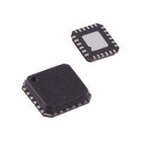
ADN2871ACPZ-RL7 Analog Devices Inc, ADN2871ACPZ-RL7 Datasheet - Page 15

ADN2871ACPZ-RL7
Manufacturer Part Number
ADN2871ACPZ-RL7
Description
IC,Laser Diode/LED Driver,LLCC,24PIN,PLASTIC
Manufacturer
Analog Devices Inc
Type
Laser Diode Driver (Fiber Optic)r
Datasheet
1.ADN2871ACPZ-RL.pdf
(20 pages)
Specifications of ADN2871ACPZ-RL7
Data Rate
4.25Gbps
Number Of Channels
1
Voltage - Supply
3 V ~ 3.6 V
Current - Supply
32mA
Current - Modulation
90mA
Current - Bias
100mA
Operating Temperature
-40°C ~ 85°C
Package / Case
24-VFQFN, CSP Exposed Pad
Mounting Type
Surface Mount
Lead Free Status / RoHS Status
Lead free / RoHS Compliant
RESISTOR SETPOINT CALIBRATION
In resistor setpoint calibration, Pin PAVREF, Pin ERREF, and
Pin RPAV must all be tied to V
extinction ratio can be set using the PAVSET and ERSET pins,
respectively. A resistor is placed between the pin and GND to
set the current flowing in each pin, as shown in Figure 30. The
ADN2871 ensures that both PAVSET and ERSET are kept 1.23 V
above GND. The PAVSET and ERSET resistors are given by
where:
R
I
P
Power-On Sequence in Resistor Setpoint Mode
After power-on, the ADN2871 starts an initial process sequence
that takes 25 ms before enabling the alarms. Therefore, the
resistors connected to Pin PAVSET and Pin ERSET should be
stabilized within 20 ms after power-on. If the PAVSET and
ERSET resistors are connected to the ADN2871 20 ms after the
power supply is turned on, the ADN2871 alarm may kick in
and assert FAIL.
I
I
resistor setpoint as described next.
Voltage Setpoint
In voltage setpoint calibration, two methods can be used for
I
Method 1: Measuring Voltage at RPAV
The I
value of RPAV (see Figure 31) as long as the laser is on and is
being controlled by the control loop. This method does not
provide a valid I
fail mode. A MicroConverter buffered ADC input can be
connected to RPAV to make this measurement. No decoupling
or filter capacitors should be placed on the RPAV node because
this can disturb the control loop.
MOD
MPD
MPD
MPD
SP
AV
Figure 31. Single Measurement of I
is the optical responsivity (in amperes per watt).
is the average power required (mW).
monitoring can be implemented for voltage setpoint and
monitoring.
is the modulation current required (mA).
MONITORING
R
R
MPD
PAVSET
ERSET
current is equal to the voltage at RPAV divided by the
=
=
1
2 .
P
MPD
AV
1
I
V
PHOTODIODE
MOD
2 .
μ
×
×
reading when the laser is in shutdown or
C ADC
INPUT
V
R
100
SP
V
CC
CC
R
1kΩ
MPD
. The average power and
at RPAV in Voltage Setpoint Mode
PAVSET
RPAV
ADN2871
Rev. A | Page 15 of 20
(Ω)
(Ω)
Method 2: Measuring I
The second method has the advantage of providing a valid I
reading at all times, but has the disadvantage of requiring a
differential measurement across a sense resistor directly in
series with the I
is placed in series with the I
has a pinout where the monitor photodiode cathode and the
lasers anode are not connected, a sense resistor, Rx, can be placed
in series with the photodiode cathode and V
Figure 33. When choosing the value of the resistor, the user
must take into account the expected I
operation. The resistor must be large enough to make a
significant signal for the buffered ADC to read, but small
enough not to cause a significant voltage reduction across the
I
250 mV when the laser is in normal operation. It is recommended
that a 10 pF capacitor be placed in parallel with the sense resistor.
MPD
. The voltage across the sense resistor should not exceed
Figure 32. Differential Measurement of I
Figure 33. Single Measurement of I
MPD
DIFFERENTIAL
µC ADC
. As shown in Figure 32, a small resistor, Rx,
µC ADC
PHOTODIODE
INPUT
INPUT
PHOTODIODE
MPD
ADN2871
MPD
Across a Sense Resistor
200Ω
ADN2871
. If the laser used in the design
Rx
200Ω
Rx
PAVSET
V
CC
V
MPD
PAVSET
CC
MPD
MPD
Across a Sense Resistor
V
Across a Sense Resistor
CC
value in normal
LD
LD
10pF
CC
, as shown in
ADN2871
MPD


