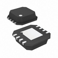
ADA4857-1YCPZ-R2 Analog Devices Inc, ADA4857-1YCPZ-R2 Datasheet - Page 17

ADA4857-1YCPZ-R2
Manufacturer Part Number
ADA4857-1YCPZ-R2
Description
4.4nV Ultralow Distortion Hgh Spd Op Amp
Manufacturer
Analog Devices Inc
Datasheet
1.ADA4857-1YCPZ-R7.pdf
(20 pages)
Specifications of ADA4857-1YCPZ-R2
Amplifier Type
Voltage Feedback
Number Of Circuits
1
Slew Rate
2800 V/µs
-3db Bandwidth
850MHz
Current - Input Bias
2µA
Voltage - Input Offset
2000µV
Current - Supply
5mA
Current - Output / Channel
50mA
Voltage - Supply, Single/dual (±)
4.5 V ~ 10.5 V, ±2.25 V ~ 5.25 V
Operating Temperature
-40°C ~ 125°C
Mounting Type
Surface Mount
Package / Case
8-LFCSP
Lead Free Status / RoHS Status
Lead free / RoHS Compliant
Output Type
-
Gain Bandwidth Product
-
Lead Free Status / RoHS Status
Lead free / RoHS Compliant
ACTIVE LOW-PASS FILTER (LPF)
Active filters are used in many applications such as antialiasing
filters and high frequency communication IF strips. With a
410 MHz gain bandwidth product and high slew rate, the
ADA4857-2 is an ideal candidate for active filters. Figure 48
shows the frequency response of 90 MHz and 45 MHz LPFs.
In addition to the bandwidth requirements, the slew rate must
be capable of supporting the full power bandwidth of the filter.
In this case, a 90 MHz bandwidth with a 2 V p-p output swing
requires at least 2800 V/μs.
The circuit shown in Figure 49 is a 4-pole, Sallen-Key LPF. The
filter comprises two identical cascaded Sallen-Key LPF sections,
each with a fixed gain of G = 2. The net gain of the filter is equal
to G = 4 or 12 dB. The actual gain shown in Figure 48 is 12 dB.
This does not take into account the output voltage being divided in
half by the series matching termination resistor, R
load resistor.
Setting the resistors equal to each other greatly simplifies the
design equations for the Sallen-Key filter. To achieve 90 MHz,
the value of R should be set to 182 Ω. However, if the value of R
is doubled, the corner frequency is cut in half to 45 MHz. This
would be an easy way to tune the filter by simply multiplying
the value of R (182 Ω) by the ratio of 90 MHz and the new
corner frequency in megahertz.
+IN1
49.9Ω
R
T
R
5.6pF
R
C2
348Ω
R2
Figure 49. 4-Pole, Sallen-Key Low-Pass Filter (ADA4857-2)
U1
+5V
–5V
T
, and the
0.1µF
0.1µF
3.9pF
348Ω
10µF
10µF
R1
C1
Rev. A | Page 17 of 20
OUT1
R
Figure 48 shows the output of each stage is of the filter and the
two different filters corresponding to R = 182 Ω and R = 365 Ω.
Resistor values are kept low for minimal noise contribution,
offset voltage, and optimal frequency response. Due to the low
capacitance values used in the filter circuit, the PCB layout and
minimization of parasitics is critical. A few picofarads can detune
the corner frequency, f
in Figure 49 actually incorporate some stray PCB capacitance.
Capacitor selection is critical for optimal filter performance.
Capacitors with low temperature coefficients, such as NPO
ceramic capacitors and silver mica, are good choices for filter
elements.
5.6pF
R
C4
348Ω
–12
–15
–18
–21
–24
–27
–30
–33
–36
–39
–42
15
12
–3
–6
–9
9
6
3
0
R4
0.1
R
V
L
S
U2
+5V
–5V
= 100Ω
= ±5V
Figure 48. Low-Pass Filter Response
3.9pF
0.1µF
0.1µF
348Ω
10µF
10µF
C3
R3
1
c
of the filter. The capacitor values shown
FREQUENCY (MHz)
ADA4857-1/ADA4857-2
49.9Ω
R
T
OUT1, f = 90MHz
OUT1, f = 45MHz
10
OUT2, f = 45MHz
OUT2
OUT2, f = 90MHz
100
500


