AD9212-65EBZ Analog Devices Inc, AD9212-65EBZ Datasheet - Page 26
AD9212-65EBZ
Manufacturer Part Number
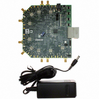
AD9212-65EBZ
Description
Octal 10 Bit, 65 MSPS Serial LVDS ADC EB
Manufacturer
Analog Devices Inc
Datasheet
1.AD9212ABCPZRL7-40.pdf
(56 pages)
Specifications of AD9212-65EBZ
Number Of Adc's
8
Number Of Bits
10
Sampling Rate (per Second)
65M
Data Interface
Serial
Inputs Per Adc
1 Differential
Input Range
2 Vpp
Power (typ) @ Conditions
100mW @ 65MSPS
Voltage Supply Source
Analog and Digital
Operating Temperature
-40°C ~ 85°C
Utilized Ic / Part
AD9212
Lead Free Status / RoHS Status
Lead free / RoHS Compliant


AD9212
Two output clocks are provided to assist in capturing data from
the AD9212. The DCO is used to clock the output data and is
equal to five times the sample clock (CLK) rate. Data is clocked
out of the AD9212 and must be captured on the rising and
Table 9. Flexible Output Test Modes
Output Test
Mode Bit
Sequence
0000
0001
0010
0011
0100
0101
0110
0111
1000
1001
1010
1011
1100
1
All test mode options except PN sequence short and PN sequence long can support 8- to 14-bit word lengths in order to verify data capture to the receiver.
Pattern Name
Off (default)
Midscale short
+Full-scale short
−Full-scale short
Checkerboard
PN sequence long
PN sequence short
One-/zero-word toggle
User input
1-/0-bit toggle
1× sync
One bit high
Mixed frequency
1
1
Digital Output Word 1
N/A
1000 0000 (8-bit)
10 0000 0000 (10-bit)
1000 0000 0000 (12-bit)
10 0000 0000 0000 (14-bit)
1111 1111 (8-bit)
11 1111 1111 (10-bit)
1111 1111 1111 (12-bit)
11 1111 1111 1111 (14-bit)
0000 0000 (8-bit)
00 0000 0000 (10-bit)
0000 0000 0000 (12-bit)
00 0000 0000 0000 (14-bit)
1010 1010 (8-bit)
10 1010 1010 (10-bit)
1010 1010 1010 (12-bit)
10 1010 1010 1010 (14-bit)
N/A
N/A
1111 1111 (8-bit)
11 1111 1111 (10-bit)
1111 1111 1111 (12-bit)
11 1111 1111 1111 (14-bit)
Register 0x19 and Register 0x1A
1010 1010 (8-bit)
10 1010 1010 (10-bit)
1010 1010 1010 (12-bit)
10 1010 1010 1010 (14-bit)
0000 1111 (8-bit)
00 0001 1111 (10-bit)
0000 0011 1111 (12-bit)
00 0000 0111 1111 (14-bit)
1000 0000 (8-bit)
10 0000 0000 (10-bit)
1000 0000 0000 (12-bit)
10 0000 0000 0000 (14-bit)
1010 0011 (8-bit)
10 0110 0011 (10-bit)
1010 0011 0011 (12-bit)
10 1000 0110 0111 (14-bit)
Rev. D | Page 26 of 56
falling edges of the DCO that supports double data rate (DDR)
capturing. The FCO is used to signal the start of a new output
byte and is equal to the sample clock rate. See the timing
diagram shown in Figure 2 for more information.
Digital Output Word 2
N/A
Same
Same
Same
0101 0101 (8-bit)
01 0101 0101 (10-bit)
0101 0101 0101 (12-bit)
01 0101 0101 0101 (14-bit)
N/A
N/A
0000 0000 (8-bit)
00 0000 0000 (10-bit)
0000 0000 0000 (12-bit)
00 0000 0000 0000 (14-bit)
Register 0x1B and Register 0x1C
N/A
N/A
N/A
N/A
Subject
to Data
Format
Select
N/A
Yes
Yes
Yes
No
Yes
Yes
No
No
No
No
No
No
Related parts for AD9212-65EBZ
Image
Part Number
Description
Manufacturer
Datasheet
Request
R

Part Number:
Description:
±1.7g Dual-Axis IMEMS Accelerometer Evaluation Board
Manufacturer:
Analog Devices Inc
Datasheet:

Part Number:
Description:
Inertial Sensor Evaluation System
Manufacturer:
Analog Devices Inc
Datasheet:
Part Number:
Description:
Manufacturer:
Analog Devices Inc
Datasheet:
Part Number:
Description:
Manufacturer:
Analog Devices Inc
Datasheet:
Part Number:
Description:
Manufacturer:
Analog Devices Inc
Datasheet:
Part Number:
Description:
Manufacturer:
Analog Devices Inc
Datasheet:
Part Number:
Description:
Manufacturer:
Analog Devices Inc
Datasheet:
Part Number:
Description:
Manufacturer:
Analog Devices Inc
Datasheet:
Part Number:
Description:
Manufacturer:
Analog Devices Inc
Datasheet:
Part Number:
Description:
Manufacturer:
Analog Devices Inc
Datasheet:
Part Number:
Description:
Manufacturer:
Analog Devices Inc
Datasheet:
Part Number:
Description:
Manufacturer:
Analog Devices Inc
Datasheet:
Part Number:
Description:
Manufacturer:
Analog Devices Inc
Datasheet: