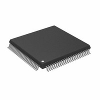
AD8191ASTZ Analog Devices Inc, AD8191ASTZ Datasheet - Page 23

AD8191ASTZ
Manufacturer Part Number
AD8191ASTZ
Description
IC,Telecom Switching Circuit,QFP,100PIN,PLASTIC
Manufacturer
Analog Devices Inc
Datasheet
1.AD8191ASTZ-RL.pdf
(32 pages)
Specifications of AD8191ASTZ
Function
Switch
Circuit
1 x 4:1
On-state Resistance
100 Ohm
Voltage Supply Source
Single Supply
Voltage - Supply, Single/dual (±)
3 V ~ 3.6 V
Operating Temperature
-40°C ~ 85°C
Mounting Type
Surface Mount
Package / Case
100-LQFP
Lead Free Status / RoHS Status
Lead free / RoHS Compliant
Available stocks
Company
Part Number
Manufacturer
Quantity
Price
Company:
Part Number:
AD8191ASTZ
Manufacturer:
ADI
Quantity:
180
Company:
Part Number:
AD8191ASTZ
Manufacturer:
Analog Devices Inc
Quantity:
10 000
Part Number:
AD8191ASTZ
Manufacturer:
ADI/亚德诺
Quantity:
20 000
Company:
Part Number:
AD8191ASTZ-RL
Manufacturer:
Analog Devices Inc
Quantity:
10 000
Company:
Part Number:
AD8191ASTZ/XST
Manufacturer:
ADI
Quantity:
210
PARALLEL INTERFACE CONFIGURATION REGISTERS
The parallel interface configuration registers can be directly set using the PP_EN, PP_CH[1:0], PP_EQ, PP_PRE[1:0], PP_OTO, and
PP_OCL pins. This interface is only accessible after the part is reset and before any registers are accessed using the serial control interface.
The state of each pin is set by tying it to 3.3 V (Logic 1) or 0 V (Logic 0).
Table 24. Parallel Interface Register Map
Name
High Speed
Device Modes
Auxiliary Device
Modes
Receiver
Settings
Input
Termination
Pulse 1
Input
Termination
Pulse 2
Receive
Equalizer 1
Receive
Equalizer 2
Transmitter
Settings
HIGH SPEED DEVICE MODES REGISTER
The high speed (TMDS) switching mode is fixed to quad mode
when using the parallel interface.
PP_EN: High Speed (TMDS) Channels Enable Bit
Table 25. PP_EN Description
PP_EN
0
1
PP_CH[1:0]: High Speed (TMDS) Switch Source Select Bus
Table 26. Quad High speed Switch Mode Mapping
PP_CH[1:0]
00
01
10
11
Description
High speed channels off, low power/standby mode
High speed channels on
O[3:0]
A[3:0]
B[3:0]
C[3:0]
D[3:0]
Bit 7
0
0
PP_EQ
PP_EQ
Description
High Speed Source A switched to
output
High Speed Source B switched to
output
High Speed Source C switched to
output
High Speed Source D switched to
output
Bit 6
High speed
switch enable
PP_EN
Auxiliary
switch enable
1
0
0
PP_EQ
PP_EQ
Source C and Source D input termination pulse-on-source switch select (termination always on)
Source A and Source B input termination pulse-on-source switch select (termination always on)
Bit 5
High speed switching
mode select (quad)
0
Auxiliary switching
mode select (quad)
0
0
0
PP_EQ
PP_EQ
Source A and Source B input equalization level select
Source C and Source D input equalization level select
Bit 4
0
0
0
0
PP_EQ
PP_EQ
Rev. 0 | Page 23 of 32
Bit 3
0
0
0
0
PP_EQ
PP_EQ
Output pre-emphasis
PP_PE[1]
AUXILIARY DEVICE MODES REGISTER
The auxiliary (low speed) switch is always enabled and the
auxiliary switching mode is fixed to quad mode when using the
parallel interface.
PP_CH[1:0]: Auxiliary Switch Source Select Bus
Table 27. Quad Auxiliary Switch Mode Mapping
PP_CH[1:0]
00
01
10
11
level select
Bit 2
0
0
0
0
PP_EQ
PP_EQ
PP_PE[0]
AUX_A[3:0]
AUX_B[3:0]0
AUX_C[3:0]
AUX_D[3:0]
AUX_COM[3:0]
Auxiliary switch source select
High speed source select
Bit 1
PP_CH[1]
PP_CH[1]
0
0
PP_EQ
PP_EQ
Output
termination
on/off select
PP_OTO
Description
Auxiliary Source A switched to
output
Auxiliary Source B switched to
output
Auxiliary Source C switched to
output
Auxiliary Source D switched to
output
Bit 0
PP_CH[0]
PP_CH[0]
Input term. on/off
select (termination
always on)
1
0
0
PP_EQ
PP_EQ
Output current level
select
PP_OCL
AD8191


